


This was the funnest part of the entire project: putting everything together!
There were a lot of steps to the final assembly. I didn't really follow any organized path to completing them, I just did things in whatever order struck my fancy. So this next section kind of jumps around a little, because I was jumping around a little.
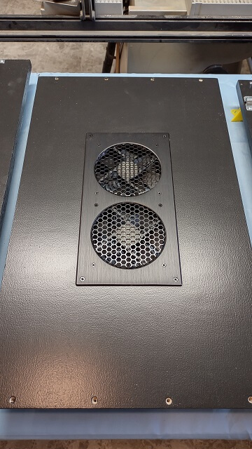
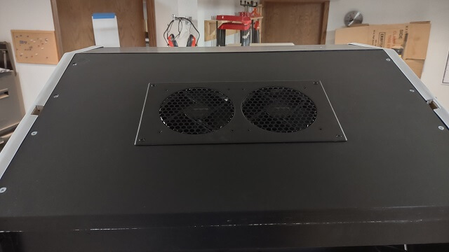
The cooling fans were installed into the top cover.
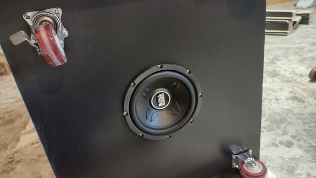
The subwoofer was installed on the bottom. Before I screwed it in place I soldered the speaker wire to the lugs. I experimented with some spade connectors, but they felt a little loose. I didn't want to risk having an intermittent connection or even having the wire fall off completely, so I went the solder route.
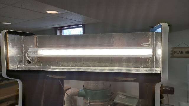
The LED light fixture was installed in the marquee area. The power cable was routed through the hole I had drilled previously, and the fixture itself was hung on some screws. I did discover that when I had pre-drilled the screw holes, I centered them in the cabinet. After I hung the light fixture I discovered that the key slots on the back of the fixture were not centered on the fixture itself. The whole fixture was shifted slightly to the right. I decided to see how everything looked before I went through the trouble of moving the screws. If it's not noticeable then I can live with the fixture being a little off center.
I took a moment to verify that the light fixture power switch was in the "on" position, then installed the marquee and the top panel. The top panel holds the marquee in place. The marquee itself just "floats" in the channels around all four sides.
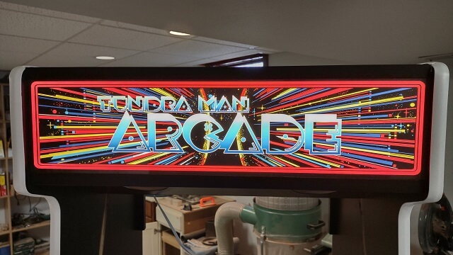
Now was a milestone moment: I plugged in the light fixture to see how the marquee looked when it was lit up. I walked around to the front of the cabinet and was astounded by how good it looked. Seriously, the picture I took doesn't do it justice.
My wife was on the phone upstairs, but I didn't care. I ran up and interrupted her phone call to have her come down to the shop and see for herself. Once she saw the marquee in its glorious lit state, she too was impressed and didn't mind the fact that I had interrupted her call.
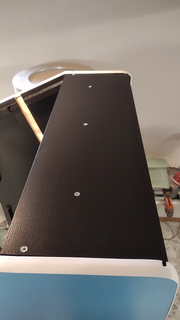
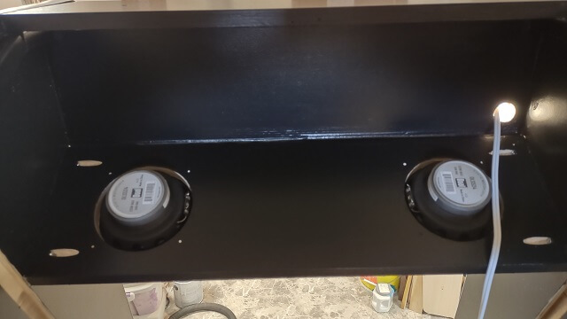
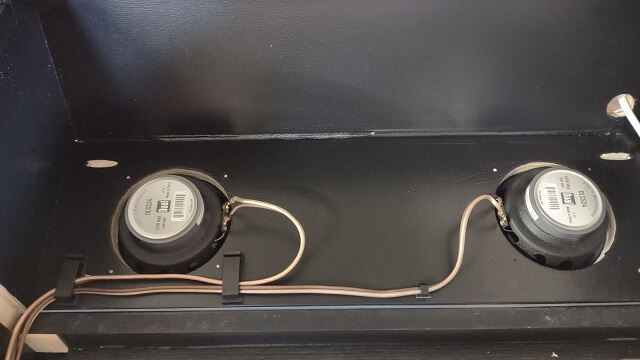
Next, I hung the speakers. I took my time screwing them in place so I didn't bung up the the screw heads as the speaker location makes them very visible. I didn't wire up the speakers yet, just got them mounted in place.
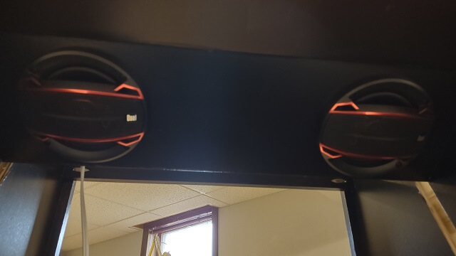
Here's what the speakers look like from the back side. As I mentioned, they weren't yet wired. Also, the power cord for the marquee light is just sitting there loose. I will tidy that up later as well.
Working my way downward, I slid the plexiglass screen cover into place. The protective plastic was removed and I tried really hard not to touch either side of the plexiglass, as I didn't want fingerprints. Also, as I've mentioned previously, plexiglass scratches if you even stare at it too intensely, so I made sure to treat it with kid gloves from this point on.
No windex and paper towels will be used to clean the plexiglass as that's a recipe for scratches. I purchased some Novus 7020 that will be used for cleaning along with a microfiber cloth. I will probably also use this stuff to clean my motorcycle windshield as well.
The picture of the plexiglass installed isn't all that interesting because, well, the plexiglass is clear. Kind of hard to make it show up in a photo.
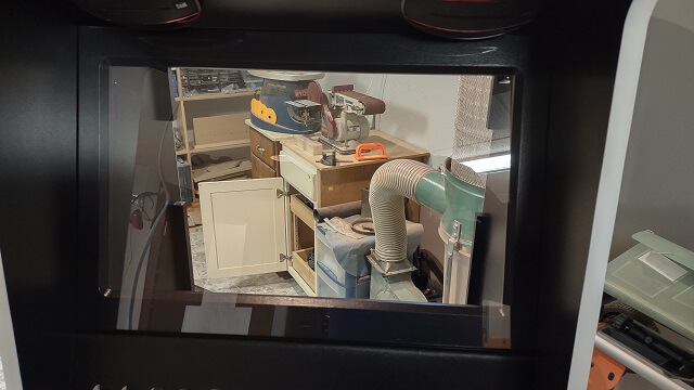
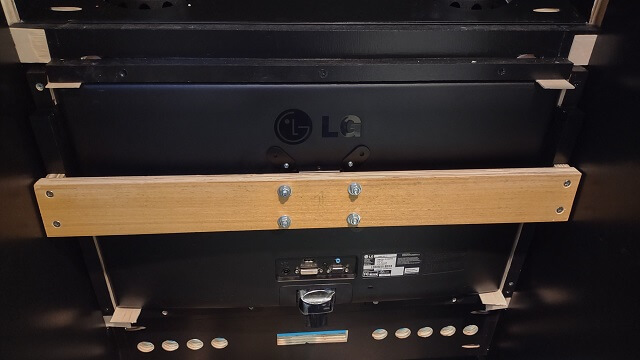
The monitor bezel was slid into place, and then the monitor was mounted to it. In order to hold the monitor tight to the bezel, and the bezel tight to the cabinet, I cut some small pieces of shims and slid them in place. You can see them in this picture.
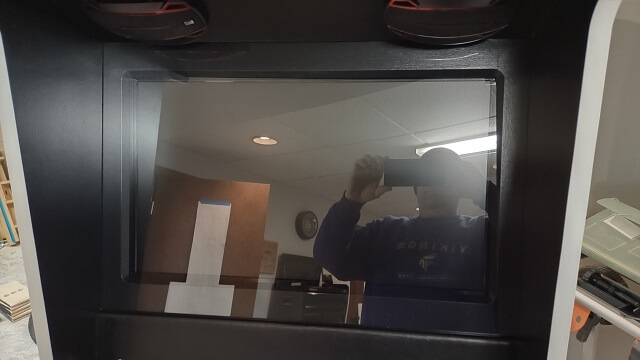
This is what the installed monitor looks like from the front of the cabinet. With everything turned off, mostly what you see right now is the reflection of my fat head.
I continued to move south and installed the keyboard tray. This proved to be very awkward as I needed to contort myself so I could screw the brackets into the underside of the cabinet. Frankly, installing these brackets was a bit more of a challenge than I expected, but after a few minutes of muttering to myself I got them in place. Then I realized I had installed them with washers intended for a different part of the project, so I had to take it apart and then re-install them. More muttering ensued.
Here's the keyboard tray in its fully extended position. It doesn't stick out very far past the front overhang of the cabinet. That's OK. I'm not intending for it to be used very much once the PC is completely configured. There's enough room for me to slide my hand in there and use the keyboard.
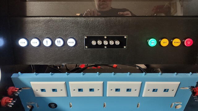
Next, I installed the lighted buttons in the back panel, along with the stereo amplifier. I'm just hanging things at this point; the wiring will come later.
Before installing, I had to disassemble each button and put an image icon inside so that once it's lit up it will indicate to the user what the button will do. Then when mounting the buttons I had to make sure the image was properly oriented. Then after all of that, I realized that with the switches installed on the back of the buttons they would interfere with each other, so the buttons had to be rotated a 1/4 turn for clearance. That meant I also had to uninstall each button, disassemble it and rotate the image icon 1/4 turn before I reassembled and reinstalled the buttons. Annoying, but necessary.
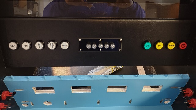
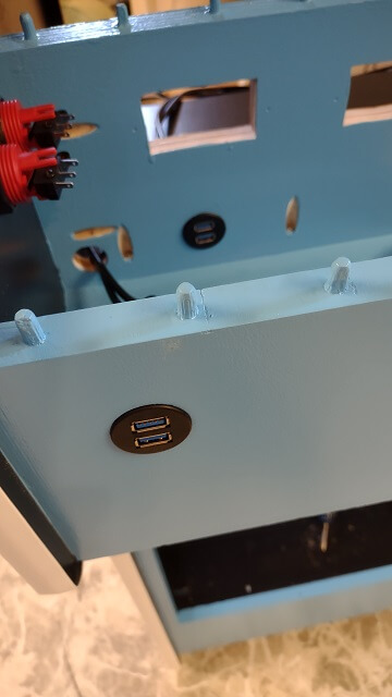
I wanted to support plugging in additional controls to the cabinet. For example, if four people wanted to play a game, I wanted to be able to plug in two game pads without having to access the back of the cabinet to find a USB port. Also, some of my controls, like the track ball, spinner and Star Wars yoke use a USB interface rather than the RJ45 connection. Because of this I wanted a USB port inside the control cavity as well. I had drilled the holes for them previously, so now I just had to mount the actual ports.
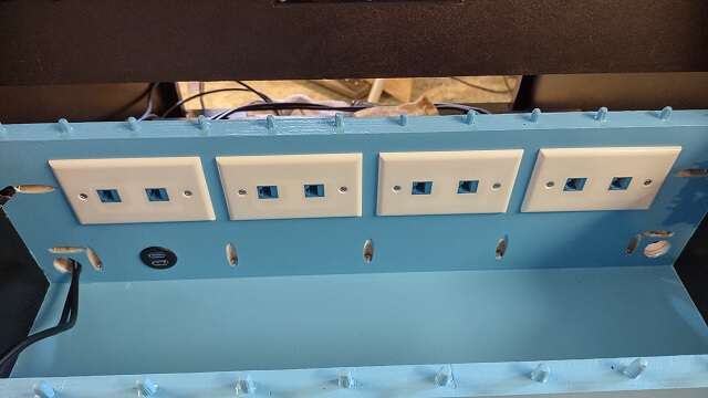
Most of the controls will plug into the cabinet via "cat 5" cables and RJ45 connections. In the control cavity I installed the RJ45 plates. Only four of the ports will initially be used, leaving a couple of extras available for future expansion.
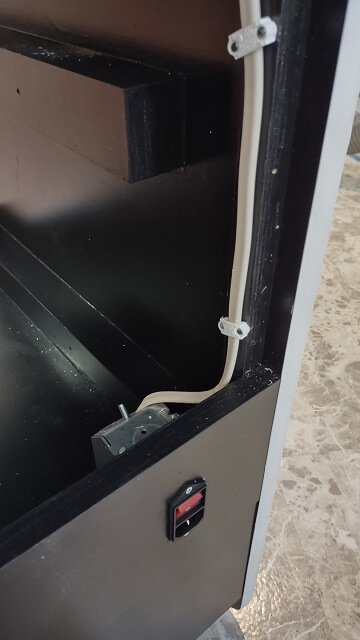
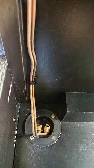
Power would be delivered to the cabinet via a "standard" IEC C14 power cord. I installed the power socket on the back of the cabinet and ran the wire up to the PC shelf. A few notes about this part of the install…
First, the power switch/female C14 socket proved to be way worse quality than what I expected. It obviously was manufactured in China to meet a price point. Frankly, I wasn't confident that the switch would hold up, so on the back side of the socket I soldered the electrical connections directly to the posts. This meant that taking the switch out of the circuit meant the socket would provide power regardless of the switch position. This was OK by me, as I didn't plan on using this switch very often. If I need to kill power to the whole cabinet I could just unplug it from the wall.
Second, trying to figure out a neat way to keep the power cable out of the way wasn't quite as straightforward as I had hoped. Standard electrical staples are about 1" long, which meant I couldn't pound them into the 3/4" cabinet wall side as they would poke through to the outside and spoil things.
So I stapled the power wire to the batten that will hold the back panel in place, taking care not to drive a staple into the same area where one of the screws would come in contact with it. The only downside to this was that the batten was slightly too narrow to mount the staple at a 90° angle, which meant I had to tilt the staples slightly. Not a big deal, I decided, as few people will ever see this part of the cabinet. Well, except for everyone on the internet looking at this picture.
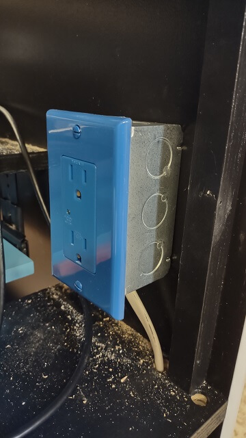
The other end of the power cable connected to an electrical box that held the outlet. This will be the power source for the PC and the IOT relay. The reason the outlet is blue is because it is a surge protected outlet. This will (hopefully) provide some protection to the PC in the event of a surge/spike rather than having it plugged straight into A/C power.
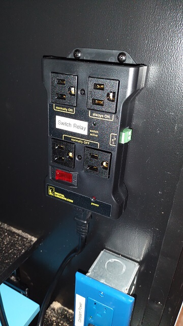
Next, I mounted the IOT Relay. This is a pretty cool piece of equipment. Basically, it plugs into the wall outlet, then other devices plug into the relay to receive power. The power to these devices is normally "off" unless the IOT relay senses a power signal on another wire, at which time it then energizes the device.
To put this another way, my plan is for everything in the cabinet to rest in a "powered off" state. Once the PC gets turned on, it will send a signal to the IOT Relay (via a USB cable) to turn on all the other devices. Likewise, when the PC gets powered off the IOT Relay will no longer sense a signal from the USB cable and will power everything off. This is my way of having a single power button to turn the entire cabinet on and off.
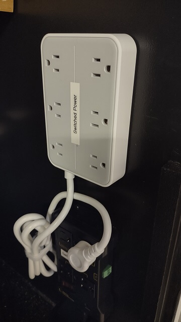
Because the IOT relay only has a couple of outlets on it, and I needed to switch six separate electrical devices, I installed an additional power strip. I got a fancy one that had additional space between the outlets, to allow plenty of room for "wall warts". This power strip plugged into the IOT device. Note that in this picture, the power strip is plugged into the wrong outlet on the IOT device. I discovered that the hard way, but you'll read about that later on.
You'll also notice that I made sure to label everything inside my cabinet. This seems like an overly OCD thing to do, but my reasoning is as follows: I put a ton of work into building this cabinet. Literally hundreds of hours. I hope that the cabinet outlives me in some form or fashion. I know what every device inside the cabinet does and controls because I was the one who installed them. However, the Tundra Boy (or whoever may inherit the cabinet after I die) probably won't know by sight what the different pieces do. So I took an extra couple of minutes to label everything and hopefully make life easier if someone else needs to do maintenance to the system.
The upper speakers were connected and the wires were run down to the amplifier. Because there was so much wiring going on inside this cabinet, I did my best to make the wire runs as neat as possible. I used different types of cable clips to try and keep things from becoming complete spaghetti inside the cabinet.
Likewise, the wire from the amplifier was run down and connected to the subwoofer in the bottom of the cabinet.
The speaker wires were then connected to the back of the amplifier.
With all of the audio hooked up, I decided I needed to test it. The amplifier supports Bluetooth, so I connected it to my phone and proceeded to play tunes through the cabinet while I continued to work. It sounded pretty decent. Obviously it wasn't going to impress an audiophile, but it jammed pretty good for an arcade cabinet.
With everything wired up at the top of the cabinet, now I could install the top fan panel. In retrospect, waiting to install this panel until later would have given me a little more light inside the panel while I wired everything else up, but it wasn't dim enough to motivate me to remove it. I also plugged in the fan to make sure it worked. It did. The dual fans were a little louder than I expected, but not to the point of being annoying.
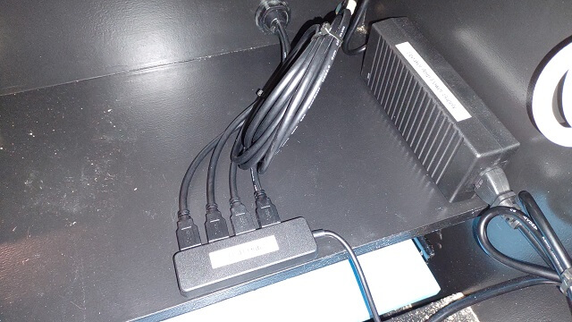
The four USB ports from the front of the cabinet (two on the front panel, two inside the control compartment) each had their own cord and plug. I didn't have enough USB ports available on my PC to plug them all in separately, so I ran them into a USB hub. That allowed those four ports to share one connection to the PC. The front ports were USB 3.0, so I made sure to get a 3.0 hub and plug that into a 3.0 port on the PC. The hub is held in place with some adhesive velcro.
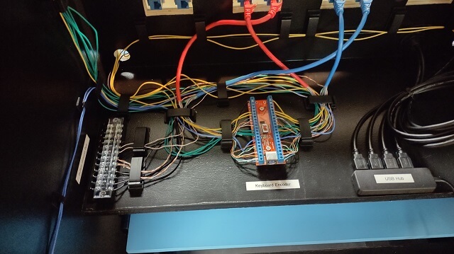
The next step was long and tedious. I had to install the keyboard encoder, and then wire it up. The keyboard encoder is the device that takes the control inputs (buttons, joysticks, etc) and converts it into a signal that the computer recognizes as a keyboard press. The game emulators then get set up to be controlled by keyboard input. To the software, it just sees that you pressed a key on the keyboard, not knowing that in real life you're pushing the joystick in a particular direction.
Each game control is a simple on/off switch. A wire runs from the keyboard encoder to the control, then the other side of the control switch is run to ground. When the encoder sees a wire has completed the circuit, it sends the corresponding key press to the PC.
This encoder connects to the PC via an old-school PS/2 cable. I purposefully went with a PS/2 connection because it handles simultaneous key presses faster than USB. There may be instances where two players are hammering on controls and I wanted to minimize latency. This limited what PC I could use, as it had to support the old PS/2 technology, but I was able to find one.
Each control shares a common ground connection on the keyboard encoder. Each control doesn't need to be grounded separately to a dedicated spot, which is nice as I didn't have to run dozens of individual ground wires. I would "chain" the grounds for all of the controls in an area (i.e. the nine control panel buttons) then run a single ground down to the keyboard controller area.
That reduced the number of ground wires to seven. Rather than trying to jam all seven wires into the single ground connection on the keyboard controller, I decided it would be cleaner to use a terminal block. I mounted the terminal block towards the side of the cabinet. I used a twelve position block as this would give me four extra ground connections should I want to add additional controls down the road.
Each of these terminal block positions are connected to each other. So I connected the seven wires to the terminal, then ran an eighth wire from the terminal block to the single ground connection on the keyboard encoder.
Then each of the cabinet buttons were connected to the appropriate spot on the keyboard controller. Then the individual wires from the Cat5 cables were also connected to the keyboard controller. There were a lot of wires running around inside that cabinet. I did my best to try and keep them neat, but it was a little unwieldy.
I did a ton of soldering on this project. The connections to the buttons and joysticks are made via spade connectors, which is handy as it allows a quick swap-out if a control gets damaged and needs to be replaced.
These spade connectors are meant to crimp onto the wire. However, historically I haven't had a lot of success with crimp-on connectors. It seems like they aren't very secure and have a tendency to come apart with little force needed. So I took the long route and soldered each spade connector to the wire. It took many hours, but I wound up with connections that I know won't come undone.
I didn't count how many wiring harnesses I made with spade connectors, but it was a lot. Each group of buttons needed one. Each control panel needed one. In the end I soldered over 200 spade connectors to wires. I enjoy soldering, but it got a little old with this project.
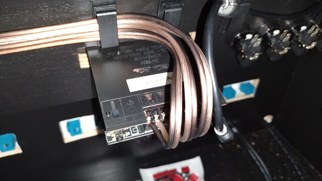
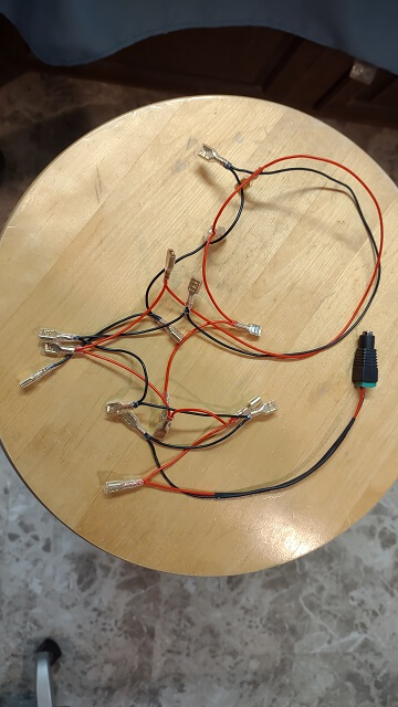
Here's an example of one of the wiring harnesses I made. This harness supplies the 5V power and ground to the illuminated control panel buttons.
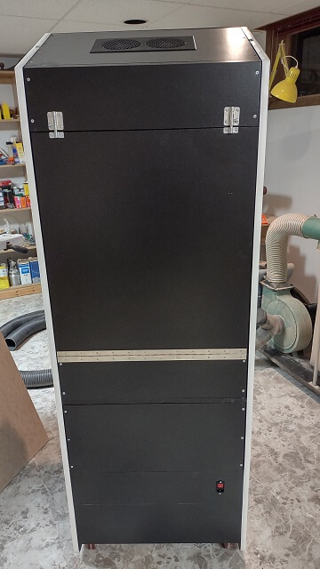
After the wiring was finally done, I installed the rear panels of the cabinet.
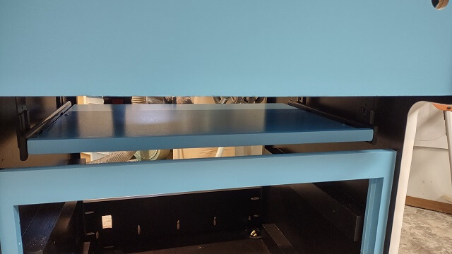
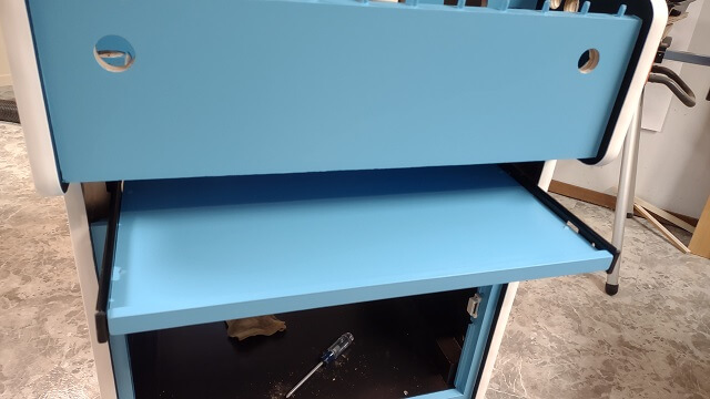
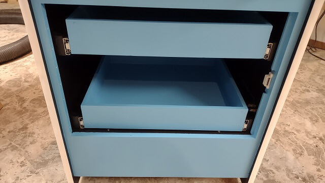
The storage drawers were installed.
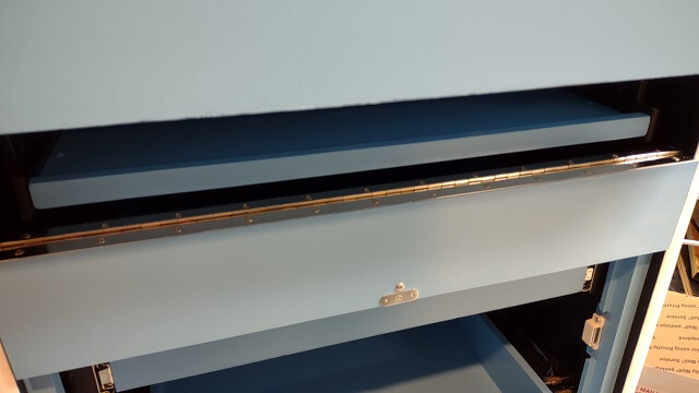
I then installed the keyboard tray door.
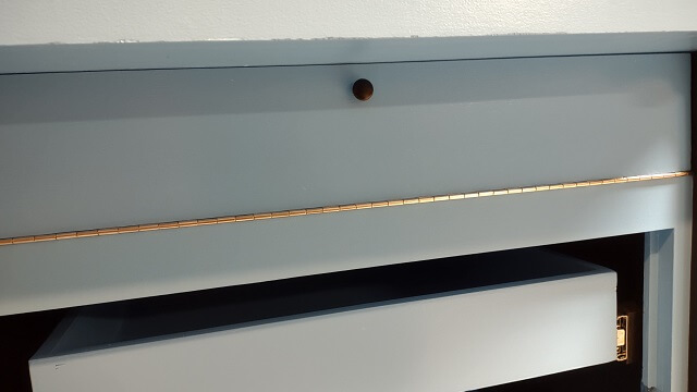
Unfortunately, I then discovered that the keyboard tray door was ever so slightly too big. It fit just fine in the space, but when I tried to swing it shut on the hinge the top of the door would hit on the cabinet. I didn't account for the length of the hypotenuse when sizing the door to the opening.
The good news is I didn't need to trim off much to make it fit. About 1/16". The bad news is I then had to repaint the piece to cover the exposed wood where I trimmed the door. But once trimmed, it fit much better and would properly close.
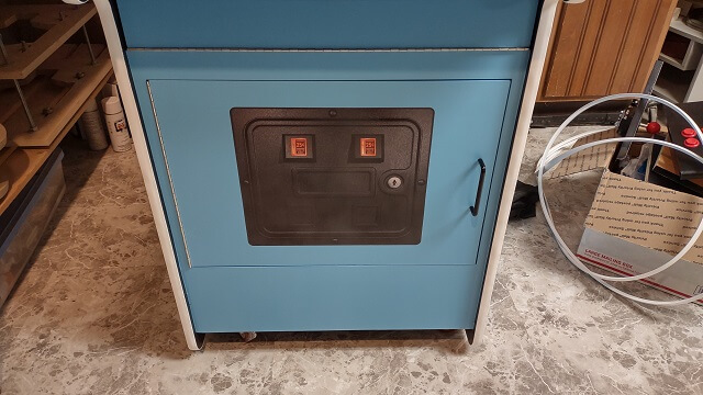
The very last piece I had to affix was the storage door. This felt like a milestone. After 2.5 years since I started building the cabinet I could officially say I was finished with the construction phase of the project. The next phase is the configuration of the software.
Not everything went as smooth as I hoped. I had to do some troubleshooting.
Return To The Main Wood Gallery
This page last updated on 09/21/2023