


The control panel modules were going to be a bunch of small panels that can be swapped in and out depending on the needs of the particular game to be played. Some of the panels would have controls mounted on them, and some will be blank to fill the edges of the panel area and/or provide spacing between the controls. I spent some time thinking about all the different control permutations I would need to play the various games.
From there, I put together a list of the various panels I would need. I calculated out a total number of linear inches of panel material, and added about 15% overage for waste. This came out to a little over 14 feet. Because the material I was cutting the panels from was 24" wide, I rounded up to 16 feet. So I needed 8 24" wide blanks. Each blank would be 11" deep. I cut out all eight blanks at the table saw.
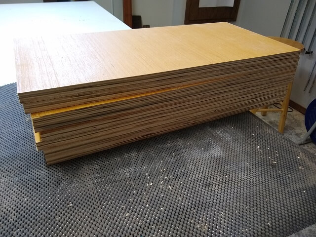
I didn't want the front edge of the control panel to have a sharp edge, as I felt that may be uncomfortable. So chucked up a 1/2" roundover bit in the router table. It would be easier to route the entire blank at once before slicing them up, versus routing the edge on all the individual pieces.
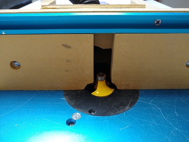
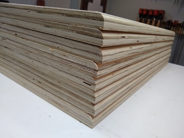
Passing each blank over the router bit gave me a stack of blanks with a nice round edge on them.
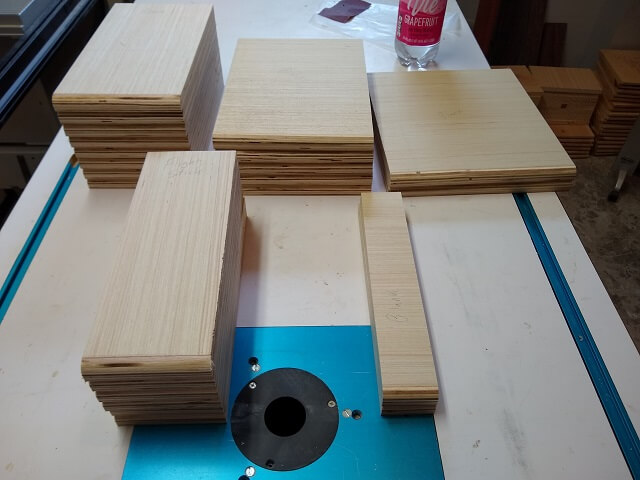
Now it was time to slice up these blanks into the various widths I would need. I went back to my calculations I had made and referenced the different sizes I would need. Here's what I came up with:
- Three 2" wide panels (all will be blanks with no controls.)
- Six 4" wide panels (two joystick, one flight stick, three blanks.)
- Eight 6" wide panels (one diagonal joystick, one spinner, two three button panels, two six button panels, two blanks.)
- Five 8" wide panels (one trackball, two 5 button panels, two blanks.)
- Two 10" wide panels (blanks only.)
With the panels cut I found I had been much more efficient with the use of the blanks than I had anticipated. I wound up with two large blank pieces left over. One was a full 24", and the other one was about 18" wide. I didn't mind having a little bit of extra material as I could always use it to add new control panels down the road. However, I really didn't feel I needed that much extra just sitting around and taking up space.
I decided to go ahead and make an extra 20" wide panel to be used to mount driving controls. I hadn't yet purchased any driving controls, but I figured I could at least put it aside for when I did want to incur the additional expense. This panel will easily be wide enough for a steering wheel, a shifter and a few buttons.
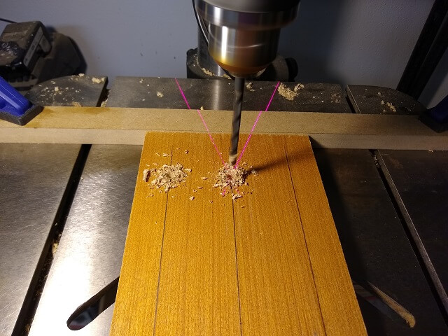
With the panels cut, it was time to drill holes in the bottom where they will slide onto the dowels. I set up a board as a fence to help me accurately position the vertical location of the hole, and used my laser crosshairs to help me position the horizontal location.
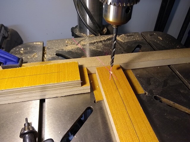
Most of the panels need multiple dowel holes, so I would keep the back of the panel tight against the fence and slide the panel sideways to the next location mark.
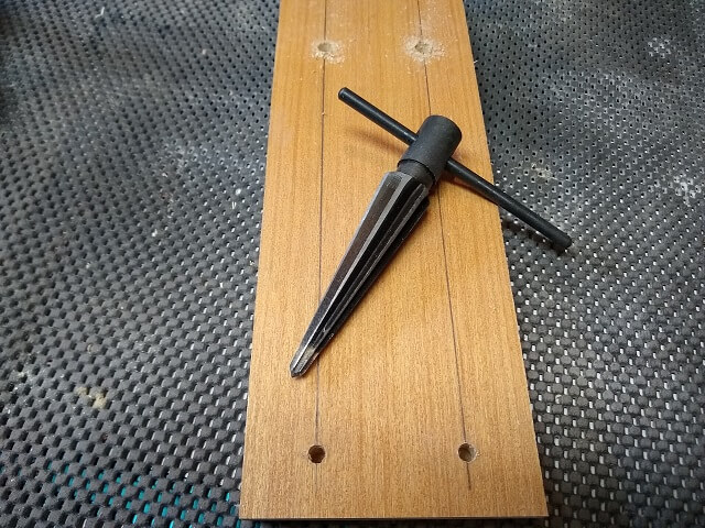
After all of the holes were drilled, I spent some time with a tapering tool to widen the outer portion of the holes. This will give a little "wiggle" room as the panels are slid into place over the dowels.
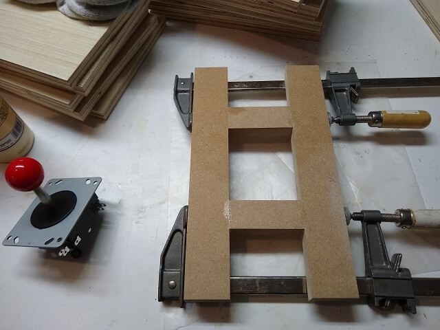
Next it was time to cut the holes and route the recesses for all of the panel controls. To route the recesses I started by building some routing jigs. This jig is for the joysticks.
This jig is for the flight stick. I only have one flight stick, but still needed to build a jig.
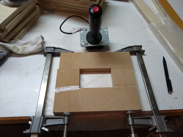
My joysticks are going to be mounted from the bottom of the panels. However, just attaching the stick to the bottom of 3/4" plywood would mean I would lose 3/4" in height when using the joystick. The joysticks were fairly tall, but 3/4" was a bit too much height for me to give up. So, I routed a recess in the bottom of the panels for the joystick to sit in. This would reduce the amount of height lost after the joysticks were mounted.
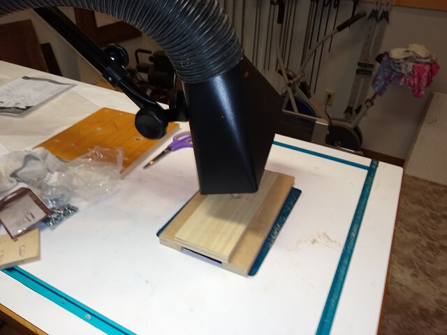
Attaching the routing templates I had made above to the panels using double-sided tape, I was then able to use a pattern cutting bit in the router table to cut the recesses. A steady stream of sawdust was spewing out of the hole that was drilled for the joystick shaft, so to keep from getting covered I used my brand new dust hood that I had just received as a Christmas gift. This sucked most of the sawdust away from my face.
One downside to using this method of routing is that you're working "blind." The wood being routed away is on the bottom side of the workpiece. Because of this, you have to go by feel and occasionally turn off the router so you can turn the workpiece over and visually gauge the progress. This makes the routing a bit slow. Thankfully I only had a few of these to do.
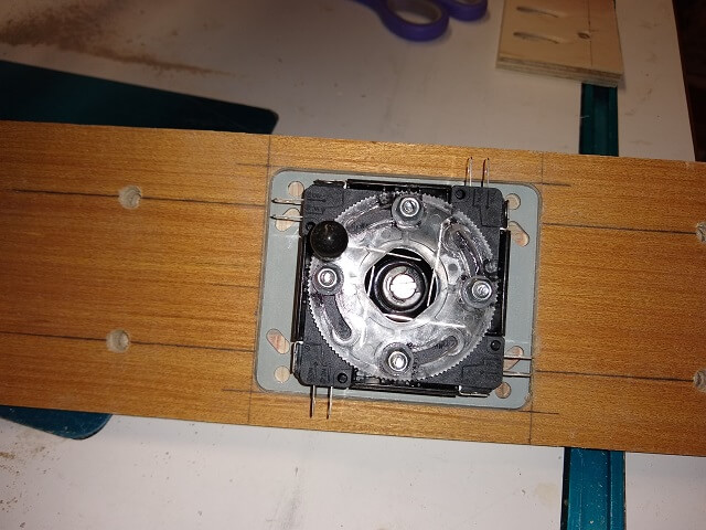
Here is one of the joysticks being test fitted in the routed recess. The recess was tight, but would work.
There are two ways to mount joysticks. By far the easiest is the "top mount" method, where holes are drilled through the workpiece and bolts are threaded from the top of the panel, then nuts are used to hold the joystick in place. The big advantage to this method is it allows for a deeper recess route, which means less joystick height is sacrificed. The big disadvantage is that there would be four mounting bolt heads visible from the top of the panel.
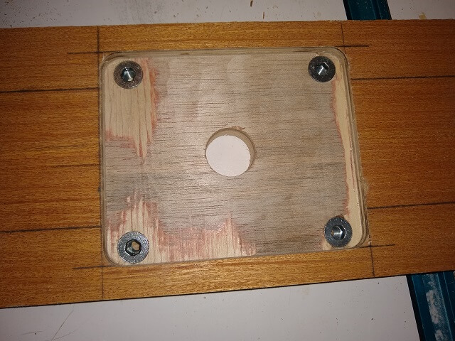
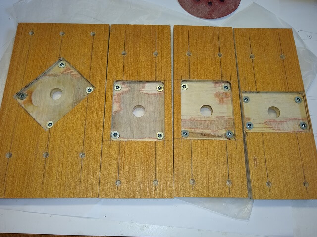
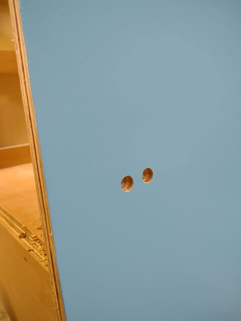
A cleaner method is to attach the joysticks from the bottom using threaded inserts. This is the method that I decided to use, as I didn't like the idea of visible bolt heads on the top of my panels. So four holes were drilled and threaded inserts were installed on the underside of the panels. Care was required to not drill the insert holes so deep that the bit would protrude from the front of the panel; this would kind of defeat the whole purpose behind rear mounting the joysticks.
This process was repeated four times for the four different joystick panels I was using. Here are all four of them lined up. The two panels in the center are standard joysticks. The panel on the left is for a diagonally mounted joystick for playing games like Q*Bert and Congo Bongo. The panel on the right is for the flight stick, which uses a different sized mounting base than the other joysticks.
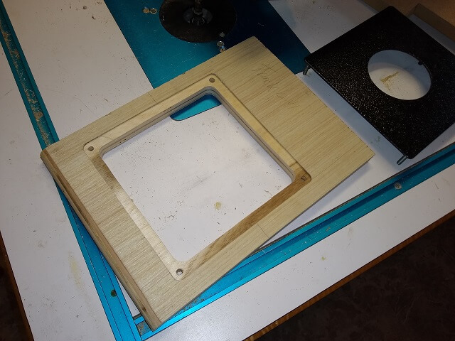
This jig is for the trackball. Like the flight stick, I only need to use this jig once. You can see in the photo I sized it to the mounting plate.
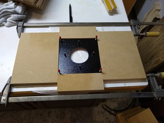
The trackball mechanism will bolt to the mounting plate, and the mounting plate will bolt to the control panel. A hole needed to be cut in the panel just slightly smaller than the mounting plate so that the trackball mechanism can pass through. After marking the lines for the hole, the scroll saw was used to cut it out.
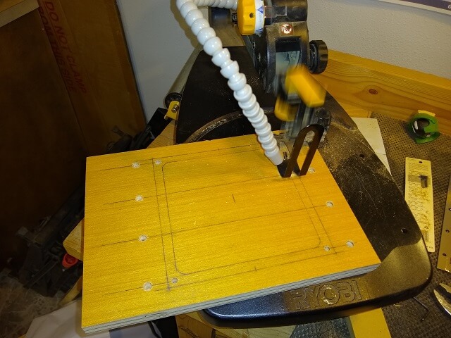
The scroll saw leaves a very clean cut, and with a little practice can be extremely accurate. Also, this is one of the few powered saws that can make an "inside" cut where a section of wood is removed from the middle of a board with no saw kerfs leading to the area where the wood is removed. This hole for the trackball assembly was just large enough, with about 1/8" clearance on each side.
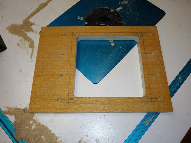
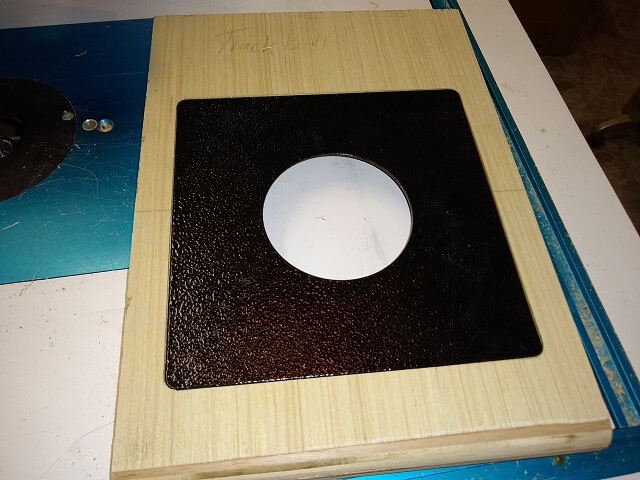
The mounting plate will be installed on the top of the panel. I could have just mounted it directly to the top without a recess, but this would have left a slight ridge around the edge of the panel. I didn't like that idea. So the above routing template was attached to the piece and a pattern cutting bit was used to make a very shallow recess. This recess is just the height of the trackball mounting plate, which was about 1/16" deep.
The mounting plate could then be set down inside of the recess and bolted to the control panel. This left the mounting plate nice and flush with the top of the wood and will allow the whole thing to be covered in vinyl without any "ridges" around the outside of the mounting plate.
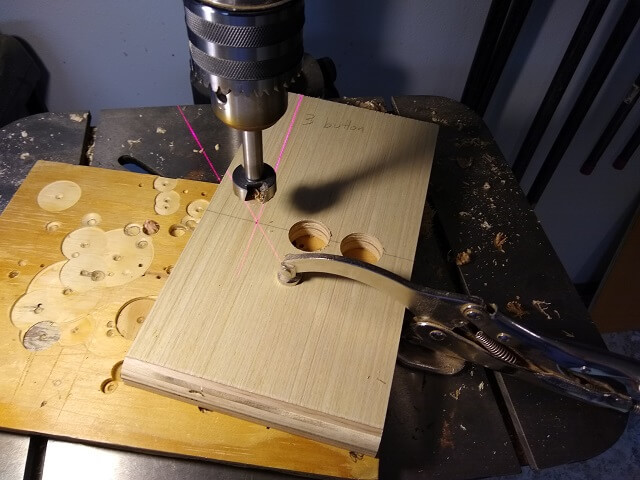
The six button panels were pretty easy to make. All that needed to be done was to mark where the buttons would be located, and drill the appropriate sized hole.
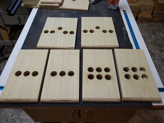
I made six button panels, in three sets of two. There are pairs so that I could have a panel of each type for two simultaneous players. The three button panels will be the ones I use most often. The six button panels will be used for games that require more than three buttons (i.e. Defender). I could have just made the six button panels, but I like the uncluttered look of the simpler panels. I also made two five button panels to mimic the original controls on some specific games such as Asteroids, Space Duel and Star Castle.
Towards the end of the project after much of the construction had been completed, I started rethinking how I would ever add foot pedals for driving games. My cabinet wouldn't have these built in, but I thought it would be handy to have the option to add them. I decided it was easier to do it now than later on, so two 1/2" holes were drilled on the lower right side of the cabinet. These two holes will allow two 1/4" female jack plugs to be mounted. I can then plug in foot controllers to these plugs as needed.
As with most of my complicated projects, it never goes as linear as depicted on a web page. I usually have multiple facets of the construction going at the same time. In this case, the finishing of the cabinet was happening in the midst of the control panel construction. The sides of the control panels were painted black as part of the finishing process. So you can see that part of the project over on the finishing page.
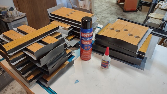
With all of the control panels built, now it was time to cover them in vinyl. I chose vinyl because I thought it would wear better. Constant rubbing of hands on black paint would likely mar quickly.
Covering the panels with vinyl turned out to be a tedious job. I kind of expected it to be, so I kept pushing it off until I had no choice but to tackle it one Saturday morning. Because I was using spray adhesive which can be messy, I wanted to do it outside. It took a full four hours, and unfortunately on the day I chose to glue the vinyl it was literally pushing 100°F outside. I got very wet with sweat.
I would cover a piece of vinyl with spray adhesive, then stick it to the panel. I would try and smooth it out, and hold the vinyl in place around the round front of the panels. After a few minutes, I would then go around the edge of the panels with CA glue to keep the vinyl from peeling at the edges. Eventually I had them all done.
This is one of those things that I wish I had done different. After I took the glued panels inside and they cooled down I noticed several of them had spots where the spray adhesive wasn't holding and the vinyl bubbled up. Unfortunately, with the edges sealed with CA I couldn't just peel these areas back and reglue. So if the bubbles bother me down the road I will probably have to rip the vinyl off and start over on the affected panels.
Perhaps the heat of the day was causing the spray adhesive to dry before I had a chance to stick the vinyl to the panel? Or maybe I didn't use enough glue? Or maybe I used the wrong type of glue? I'm not sure. Every project I build seems to have something that I'm not 100% happy about, and the vinyl on the control panels is the one on this project.
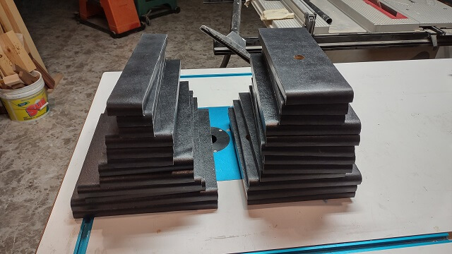
Moving on with life, once the CA had cured, I spent another couple of mind-numbing hours with an X-Acto knife trimming the vinyl flush with the edges of the control panel. Here's about a third of the panels after they had been trimmed:
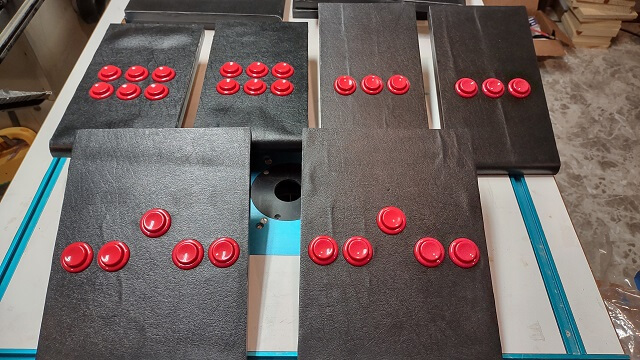
Once the trimming was done, a more fun part of the project could commence: mounting the controls. This was a bit more interesting. Here's the six button panels with the buttons mounting in them. You can see some of the vinyl bubbling in this photo.
One unexpected "gotcha" occurred with the flight stick, combined with the extremely slow speed at which I worked on this arcade cabinet project. When I was figuring out how to mount the controls to the panels, I discovered I needed to disassemble the flight stick to bottom-mount it. Rather than putting the flight stick back together right away, I left it disassembled. Fast forward nearly two years later, and I couldn't remember how it went back together. There were a bunch of parts, and I spent several hours attempting various permutations until I finally figured out the puzzle.
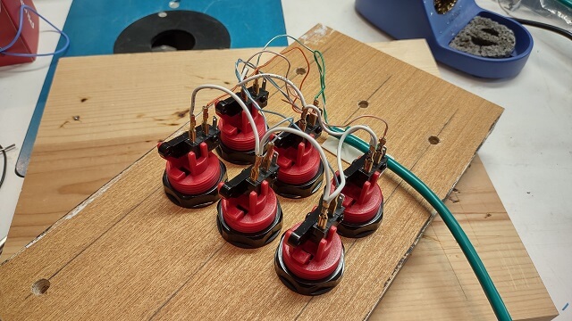
After all of the controls were mounted, it was then time to wire them up. This was another long and tedious part of the project, but it needed to be done. The Cat5 cables were stripped back so I could use the individual wires. Spade connectors were soldered onto the wires, and then connected to the button switches. The Cat5 cable was then tightly zip tied to a couple of adhesive cable mounts. These would provide some strain relief so if the cable gets pulled it won't yank the connections off the switches.
Here's one of the button panels after I wired it up:
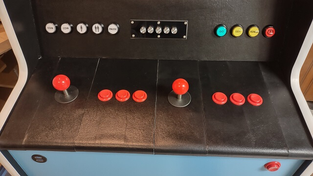
After many hours of soldering, I finally got the panels all wired. I could then ceremoniously put some of them on the cabinet and cover the gaping hole of the control area.
We're on the home stretch now! Let's wrap this project up.
Return To The Main Wood Gallery
This page last updated on 09/21/2023