


It was time to actually start building the cabinet! On this page I will describe the building of the cabinet sides, and some of the sub-assemblies that I made.
Because my "plans" weren't complete down to every single panel, I did some rough guesstimation and figured I would probably need about three full 4' X 8' sheets of plywood. At minimum, this would give me a good starting point. I might wind up needing a fourth sheet before it's all said and done, but I can always go buy more. I borrowed my brother's truck and went to the home center where I purchased the wood.
I can tell I'm not as young as I used to be, as wrestling 70 lbs sheets of plywood onto the cart, then into the truck, then into the garage isn't as easy as it was when I was younger. And I can't say it was real easy then, either.
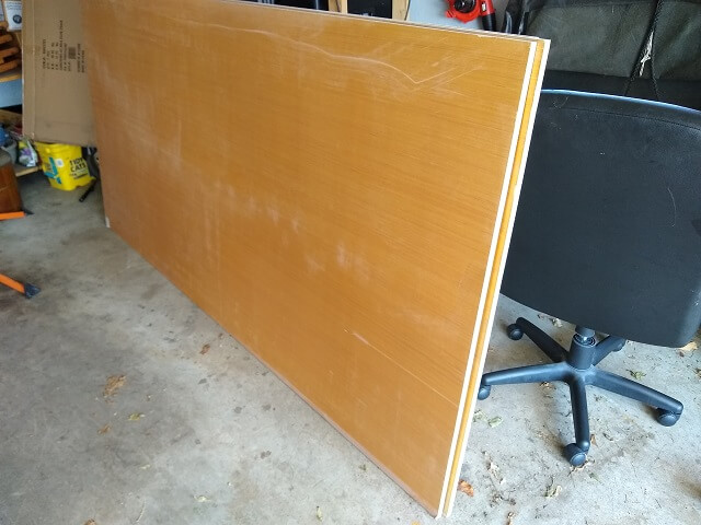
Because of the way my basement stairs are configured, there is no practical way to get a 4' x 8' sheet of 3/4" plywood down into my shop. You might be able to get a 1/4" thick sheet down there because it will bend a little, but 3/4" simply isn't happening. Because of this, I chose to cut the plywood into more manageable pieces out in the driveway and then haul those smaller pieces down to the shop. Thankfully, the day I bought the plywood happened to be an unseasonably warm March day (60s) so it was conducive to spending a couple hours out in the sunny driveway.
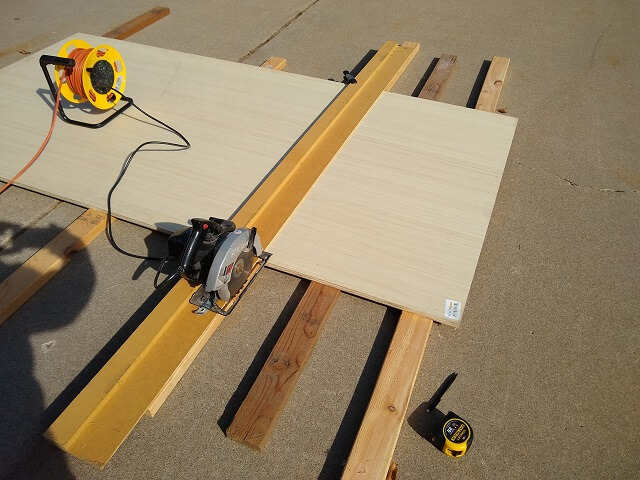
To do this, I use what's known as a "sawboard". You can Google this term and find plenty of descriptions of what they are and how to build your own, so I'm not going to go into great detail. However, I will say that they are a way to use a circular saw to make extremely straight cuts that rival the accuracy of any table saw.
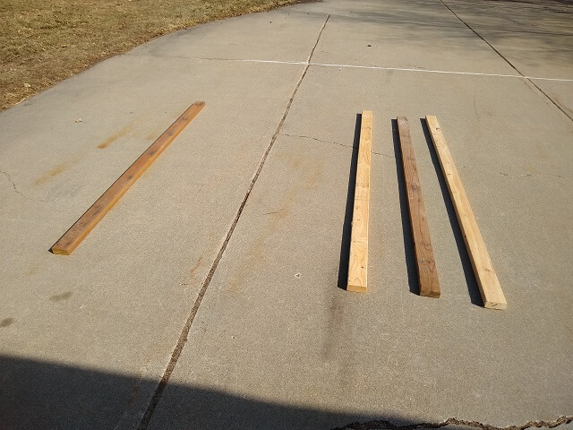
Lots of people like to work on sawhorses, but I find when cutting up full size sheet goods it's easier for me to just do it right on the ground. I do put down some scrap 2x4s to lift up the plywood slightly so the circular saw blade has some clearance without hitting the concrete.
My cabinet was going to be exactly 6' tall, so I began by cutting one of the plywood sheets to be only 6' long.
I then spun the sheet around and cut it to the proper width. The widest portion of the cabinet was going to be 28" deep, so I cut the plywood accordingly.
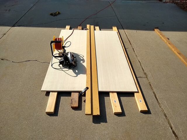
Now I had one piece the exact height and width of one cabinet side. I hauled it down to the shop, and also carried the off-cuts down. The off-cuts will be used to make some of the smaller pieces of the cabinet.
The exact same process was repeated with another sheet of plywood in order to make the second side of the cabinet.
The third piece of plywood I simply cut it in half lengthwise. Well, almost in half. One of the pieces was exactly 24" wide, while the other piece was slightly less due to the blade kerf. I was able to finagle these two half pieces of plywood down into the shop.
The next day I was reminded of how many times I crouched down and stood back up while cutting up this plywood. But it was probably good for me. I should cut up plywood more often just to keep myself in better shape.
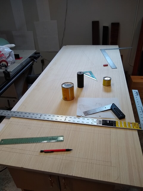
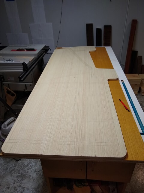
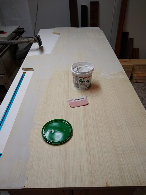
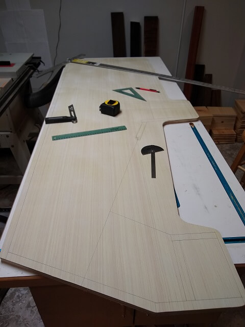
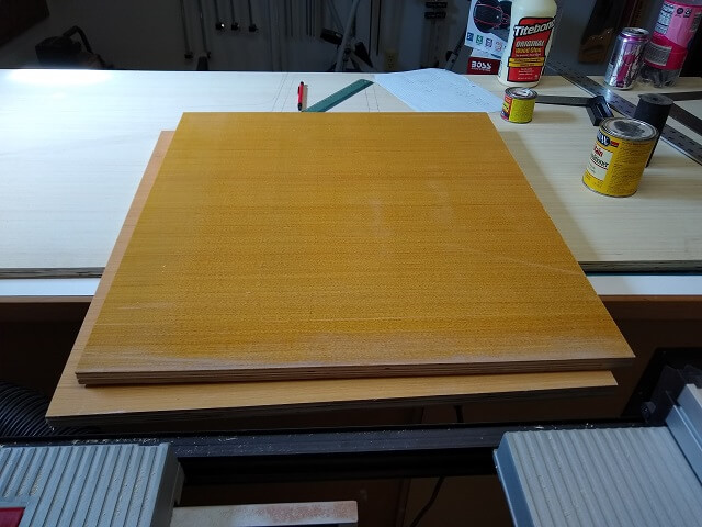
I had roughed out a design on some graph paper, so next I took one of the plywood sides and proceeded to transfer my plans to full-size. As I was doing this, a few flaws in my design became apparent so I did quite a bit of erasing and reworking. In the end, the rough outline of the cabinet remained somewhat close to original, but all of the measurements changed a little. All of the inside markings changed quite a bit.
By the way, the round items sitting on top of the wood were what I used to round off corners when I was drawing everything out.
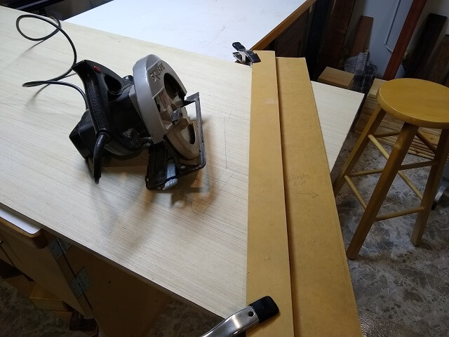
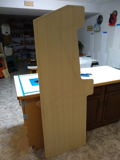
With my "design" finalized, it was time to start cutting the first side to shape. For the lines that were supposed to be straight, I wanted to use a sawboard and the circular saw to ensure they remained perfectly true. I've found that no matter how carefully I try to cut with a jigsaw, it will always have a little bit of variance (even when I use a fence with the jigsaw.) A sawboard and a circular saw has much less wander.
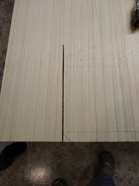
Some of the straight areas were only straight for a short stretch. In those cases, I used a sawboard but then stopped cutting once the end of the straight portion was reached.
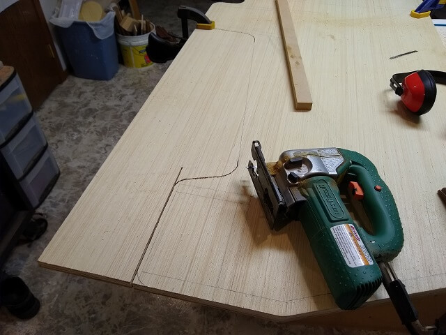
With all the straight cuts done, I then turned to the jigsaw to do the round portions of the cuts.
I then fine tuned the curves with some sandpaper until they looked pretty good. I now had one complete side of the cabinet cut to shape. I can then use this side to make a mirror image on the other cabinet side.
The easiest way to copy the shape of the first cabinet side onto the second piece of plywood is to lay it on top and trace the outline with a pencil. I lined up the flat straight edges of the rear and bottom of the two pieces, then traced all the spots where the two didn't line up.
A jigsaw was used to cut out the rough outline of the cabinet. I wasn't trying to be perfect here, and purposefully stayed about 1/8" outside of my line.
Now to make it perfect I used a flush trim bit in the router. This created two cabinet sides that were absolutely identical.
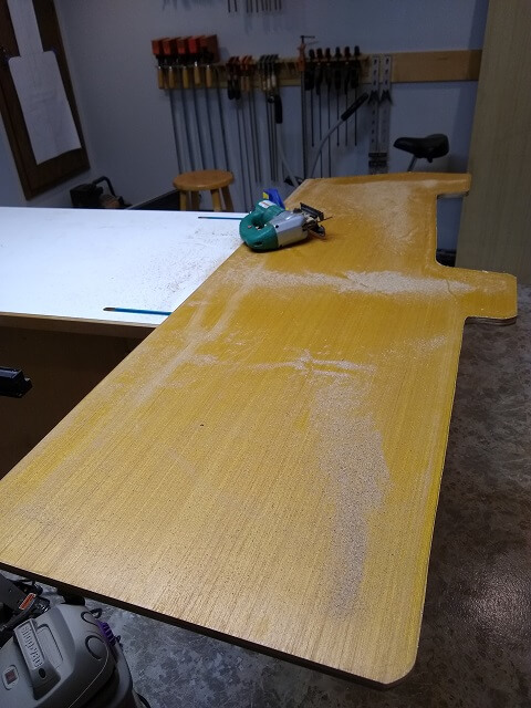
One of the keys to a nice smooth finish on wood is to fill the grain. This can be a tedious process if you're finishing the wood clear, but in this case I would be painting it with an opaque finish. So I decided to try a new method of grain filling and use drywall mud. This stuff is cheap, goes on easy, dries quickly and sands easily. The only real downside is that it creates a ton of dust when you sand it, but I'm hoping the vacuum on my sander will take care of most of that dust.
The only portion of the inside face of the cabinet sides that will be visible is the slight edge protruding from the front, and the sides next to the screen. Those were the only areas that really needed to be grain filled, as the rest would rarely be seen. I went ahead and filled the entire inside surface, I guess because I'm a little OCD.
I'm filling the grain now because it's a lot easier to do it when it's one big flat surface. Once I start putting the cabinet pieces together it would take a lot more time to fill the grain.
Once the drywall mud was dry I sanded it smooth. Now I had to transfer all my layout lines from my first panel to the second. This took a lot more time than I anticipated, especially trying to get the angled monitor line identical. I wound up spending an entire evening just going back and forth, measuring and drawing lines. Lots of erasing was done as well when I would double-check things and find discrepancies.
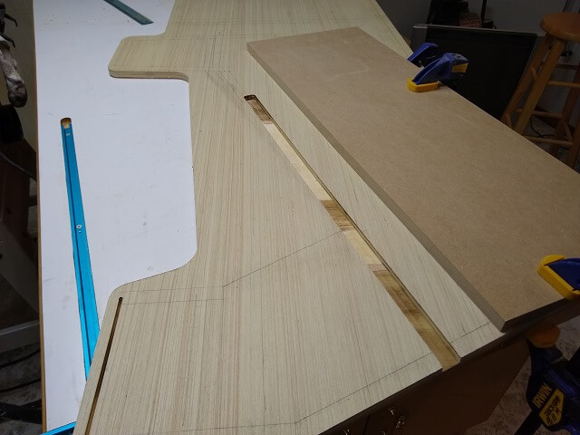
I designed the monitor bezel to slide into channels on each side of the arcade cabinet. This should make for a nice clean look once the cabinet is finished. Now it was time to route these slots, which for some reason had me a bit nervous.
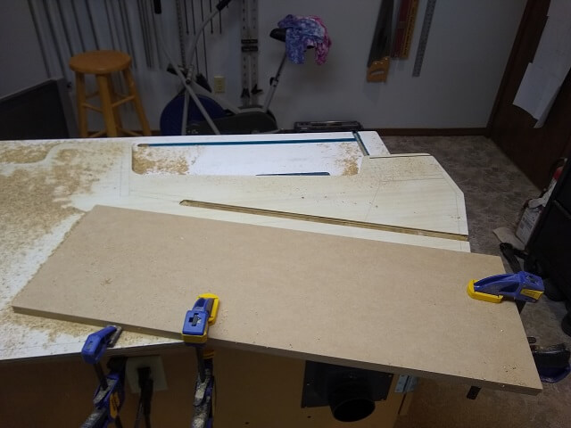
In the end, it took about an hour but it was really no big deal. I clamped a piece of MDF with a nice straight edge to the cabinet in the proper place so the edge of the router bit would cut exactly on the line I had marked. Then I simply turned the router on and ran it along the makeshift fence, making sure to keep pressure up against the fence so that my line was perfectly straight.
The channel needed to be 3/8" deep. To save wear on my router and bits I made two passes of about 3/16" deep until I reached final depth. Also, I was using a 1/2" bit and my channel needed to be 7/8" wide (3/4" MDF bezel + 1/16" plexiglass + 1/16" extra to let it slide in and out freely) so that meant after I had a 1/2" channel cut to full depth, I had to reset the MDF guide piece and make two more passes.
Then I basically did the same thing a 2nd time on the other cabinet side, only as a mirror image.
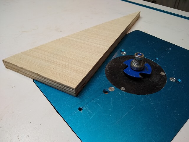
To cover up the unsightly edges in my plywood I will be using T-molding. This is basically a plastic edging that has a barbed strip on the back side. This barbed strip gets hammered into a 1/16" slot in the wood.
I bought an inexpensive slot cutting router bit set from Harbor Freight. I took it out and installed the 1/16" cutter onto the arbor. Frankly, the way the cutter, bearing, spacers, and nut all fit together felt a little janky, but I reasoned it would be OK for this one project I was planning on using it.
Also, I noticed that the bearing that came with the slot cutting set was small. It pretty much was about the same size as you would find on any other router bit that uses a bearing. On a slot cutting bit, the bearing size is what determines the depth of cut, with a smaller bearing making the bit cut deeper and vice-versa. The bearing that came with this slot cutter set made a depth of cut of about 5/8", which is really deep. The T-molding I had bought had a tang that was slightly longer than 1/4", which meant the slot cut from this router bit would wind up about twice as deep as I needed.
I reasoned this was no big deal as any extra depth would get covered up by the molding anyway. I proceeded to chuck the bit in the router table. Because of the big diameter of this bit I did reduce the speed on my router. Large diameter bits don't like super-high RPMs.
In order for the T-molding to not hang over one side of the plywood and be too short on the other, the slot needed to be exactly in the center of the plywood. Obviously I didn't want to start routing on my cabinet only to figure out I was off by a little bit, so I grabbed a piece of scrap wood and started making test cuts.
I think I adjusted the bit height about four times until I was reasonably satisfied that I was cutting a slot exactly in the center. I cut off a small piece of T-molding that I could use to test fit in my slots as I decided whether I had to raise or lower the bit.
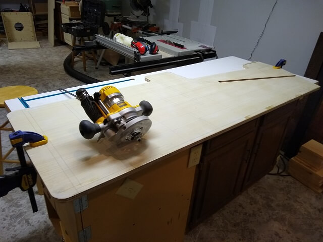
I then put one of the cabinet sides on my router table. I'm blessed in that my router table is built into one side of my workbench so if I clear everything off I can use it to route really large workpieces without too much trouble. You wouldn't want to use this method if you have one of those little bench top router tables.
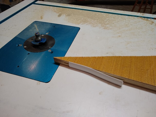
I started cutting. The first thing I noticed was how hard the router was working to route that crazy deep channel. I don't have a small router (2.5 HP) and it was noticeably struggling. I tried to go slow. I made it a couple of feet when something didn't seem right so I turned off the router and examined.
The slot I had been routing was visibly off-center. It started out centered, but then drifted. In trying to figure out how this happened, I postulated that as I routed far enough so that the plywood was hanging off the edge of the table it was causing the workpiece to bend slightly and lift the bottom of the plywood off the table slightly. This in turn would cause the slot to not be in the center of the edge.
So I guess using the router table on a piece this large maybe wasn't such a good idea? I like using the router table whenever possible, but apparently this wasn't going to work for this operation. I pulled the router out of the fixed base attached to the table and put it in the plunge base. I reasoned that if there were any slight bows to the plywood, running the router on the surface of the wood would compensate for these slight variations and keep the slot centered.
I started routing again with the plunge base. That depth of cut made me pretty uncomfortable holding the router in my hand, especially when first getting the cut started. I finished routing most of the back edge of the piece when I stopped and examined my slot. It was noticeably wavy and off center again. Arrgh!
The good news was this was on the back of the cabinet (I started there on purpose.) The bad news was it was so far off center that I couldn't live with it. So I stopped cutting slots for the time being and switched my attention to repairing the damage.
Normally I prefer to use wood to fill defects like these. However, the slot was so crooked that it would have been difficult to get a single piece of wood glued into it. And frankly at this point I was frustrated and my frustration made me a little lazy. I decided just to fill the whole slot with epoxy.
As it turns out, that slot was deep enough that it took a lot of epoxy to fill it all (about 5 oz total.) It also took three different sessions of pouring the epoxy into the slot and letting it settle to the bottom. Then after 24 hours I would come back and apply another layer. Once it was all filled to the top I sanded any excess epoxy off the edge until I was pretty much back to where I started.
So what was the cause of the slot drifting out of center? I'm not 100% sure, but I think it was a combination of a cheap router bit along with an extremely aggressive depth of cut. This is just conjecture, as I haven't come up with a better hypothesis yet.
I thought about buying a larger bearing for the Harbor Freight bit. However, that wouldn't make me feel better about the other parts of the bit that didn't seem to be of good quality. Instead, I decided to bite the bullet and order another bit with the correct size bearing from a reliable vendor who I have used before.
A single 1/16" slot cutting bit with an arbor and a bearing cost me as much as the entire Harbor Freight set that contained about 8 bits plus a wooden case. However, a tool at any price is not a value if it doesn't work. I should have heeded the old tool adage: "Buy a quality tool and you only cry once. Buy a cheap tool and you cry every time you use it." In my case, I wound up spending twice the money as I would have had I bought the nice router bit up front.

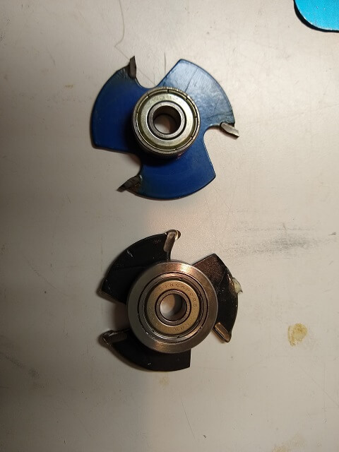
Here is a comparison of the Harbor Freight bit (top) with the Katana bit (bottom). The difference in the bearing size is very obvious, and will cause the new router bit to cut about a 1/4" shallower slot. Also not pictured, the Katana came with only two spacer washers, where the HF bit came with (not exaggerating) about 10 which needed to be stacked precariously on top of each other in order to get the nut to not bottom out in the threads before getting tight. Note that in this picture the Katana bit still had the cosmoline protective coating on it, so that's why it looks a bit goopy.
I chucked up the new bit and set the depth. A test route on a piece of scrap produced spot-on results.
I then routed the slot all the way around the edge of both sides of the cabinet. The difference was night and day between the cheap and good router bits. Even with the nice bit I took it slow as a 3/8" deep slot was still a lot of wood to hog out at once, as evidenced by the amount of sawdust I was covered in after I finished. Also, the whole shop had filled with smoke (yes, I did have the bit installed in the correct direction.) I had noticed when doing other cutting and routing operations that this plywood likes to produce smoke. Thankfully, routing these slots was the last thing I was doing this particular evening so I could close the shop door and let the smoke settle before I breathed too much of it.
Before I started attaching the two sides together I decided it would be easier to build some of the "in between" sections as sub-assemblies. Then I could attach all the parts of those sub assemblies at the same time, rather than sticking them together piece by piece.
I wanted a subwoofer in my cabinet. Is this practical? Probably not, but then again neither is building a full-size arcade cabinet. I thought it would be fun to not just hear Donkey Kong throwing his temper tantrum, but feel it too.
However, knowing that most of the games I would be playing are around 40 years old, I also realized the dynamic range of the sound effects probably don't go that deep. A 15" subwoofer would be absolute overkill. I decided an 8" woofer would be a good compromise.
I used some online speaker enclosure calculators where I could input the specs on my woofer, and it came out to needing about two cubic feet of space inside the enclosure. My design has just a hair under that amount, but it should be close enough.
The woofer box is going to be the bottom layer of my cabinet, with the speaker firing downward. I cut two pieces of plywood 24" wide and 22" deep. This would be the top and bottom of the speaker box.
I picked one of the pieces to be the bottom, and used my compass to mark a circle 7.25" in diameter. This would be the hole for the subwoofer speaker. Obviously, there are no 7.25" drill bits available. I did have a circle cutter for the drill press, but the size of the piece was too deep to fit the throat of my drill press.
In the end I decided to just cut it out with my jigsaw. Would it be exact? No. With the speaker mounted in the hole would anyone ever know? No. As my dad used to say, "It's close enough for government work."
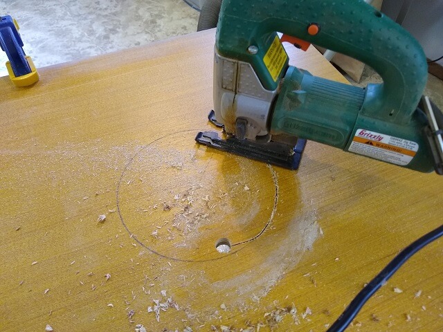
With the hole cut, I set the speaker in place and marked the holes for the mounting screws.

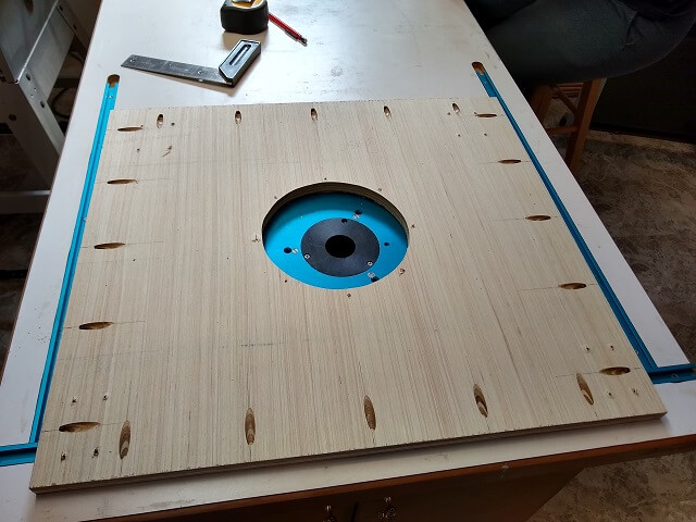
The bottom of the subwoofer enclosure will also be where the casters are mounted. I did some calculating to ensure the swivel casters wouldn't hit the side of the cabinet once the enclosure was installed. Then I marked the bottom and drilled the holes. I figured it was easier to do this now than when the cabinet was put together.
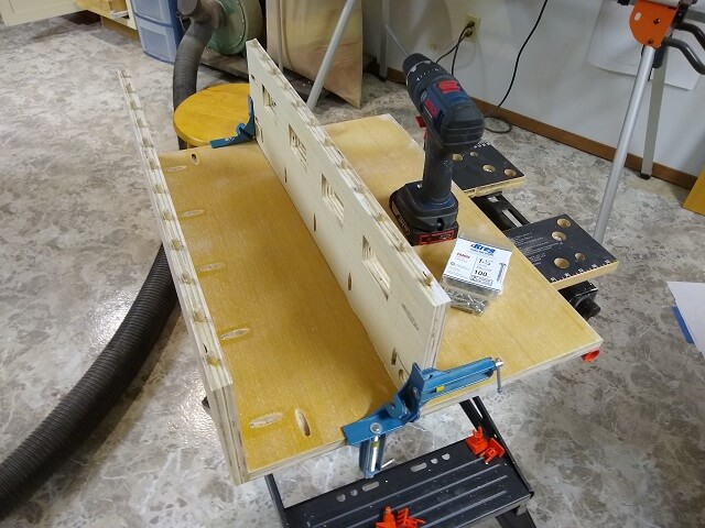
The subwoofer enclosure will be attached to the cabinet sides using pocket screws. I drilled all the pocket screw holes now so that later I can just line things up and screw the enclosure into place.
I then attached the front side of the subwoofer enclosure using pocket screws. I also put a coat of glue on the joint for added strength.
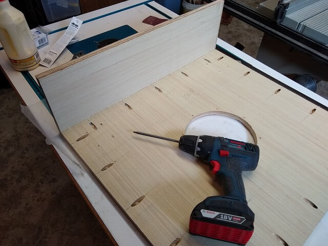
Then I repeated the process for the back side of the subwoofer enclosure.
In the top panel I drilled a 1.875" hole for the wire connection plate that will get installed later on. I also went ahead and drilled the mounting holes for the plate. I figure the more holes I drill now, the faster things will go later on when I'm getting anxious to finish the project.
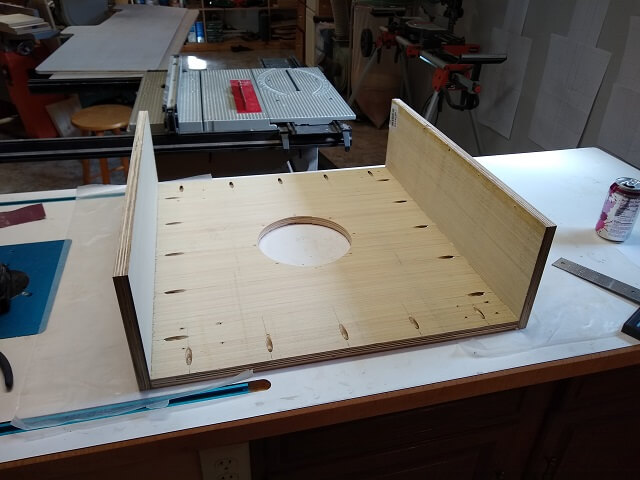
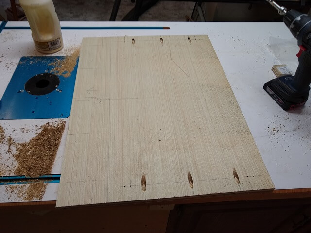
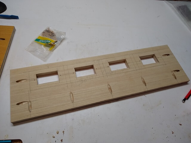
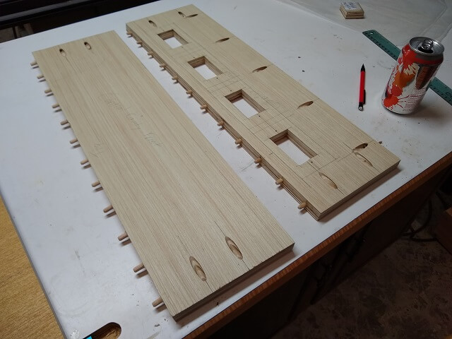
My design has a cavity below the control panel to give room for the joystick/buttons/trackball/spinner/etc to hang down on the underside of the panel. It also will contain the RJ45 ports to allow the hot swapping of the controls. On the back side of the cavity will be a shelf where I can mount the controller interfaces, and any other components that need a place to be mounted inside the cabinet.
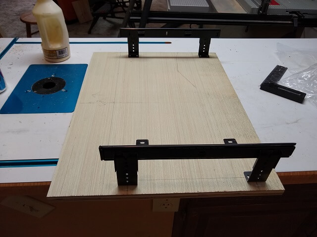
I cut the piece that will be at the bottom of this assembly. This bottom piece will also be the top side of the keyboard/mouse tray, which means the keyboard tray sliders will mount to the bottom side of this piece. I did a lot of careful measuring and then marked and drilled the holes for the keyboard tray.
Like most everything else, this piece will be connected to the other pieces using pocket holes. The front side of the piece will overhang the front of the cabinet by 4". So I drilled the pocket holes in this section so they would be inside the enclosure and not visible from outside of the cabinet (even though a person would have to bend over and look up to see them if I did leave them on the outside.)
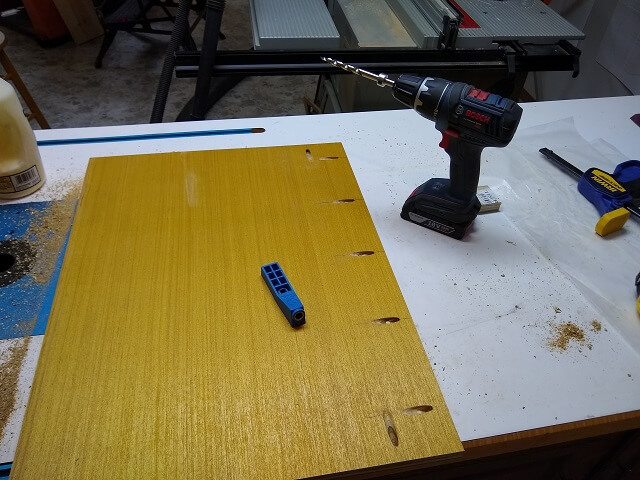
For the remainder of the pocket holes, I wanted them to be on the underside of the panel so they wouldn't be visible on the shelf in the back of the cabinet. Not that it really matters, because it's the inside of the cabinet and nobody will ever see it but me. But at least I'll know it's a little cleaner looking.
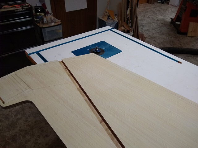
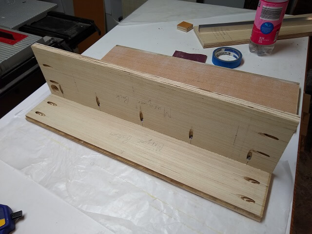
The control panel will have a slight angle to it to make it a little more comfortable while playing. The slope is about a 1:12 ratio, which means 12" from the front edge of the panel, the control surface will have raised an inch. The control panels aren't going to be quite that long, but you get what I mean.
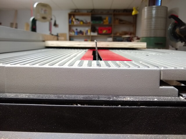
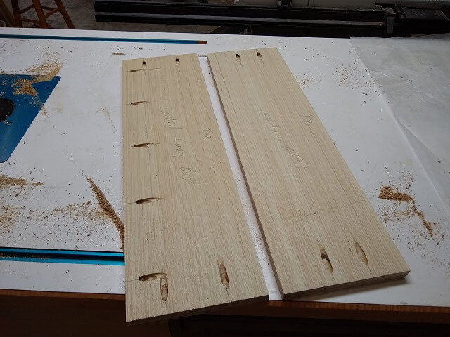
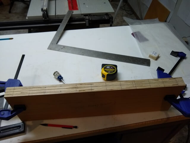
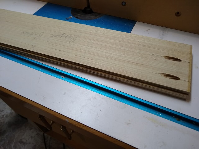
So, that means that the front and back pieces that will hold the control panels in place will need one edge cut at an angle. I measured out this angle to be 83.5°. I set the saw blade to the angle and made the cut. Because this one cut made the angle on two pieces, I only had to do this once. The angle is slight, but if you look at the picture closely you can see it.
The front and back of the cavity enclosure had their pocket holes drilled. I had to make sure I drilled them on the correct side so once mounted the angle on the top edge would be oriented in the right direction.
Because the controls (joysticks, buttons, trackball, etc.) will be swappable, a method is needed to allow the wires to be quickly connected and disconnected. RJ45 connectors like you would find on an Ethernet cable will work well for this purpose. To give them a place to connect I will be mounting RJ45 wall plates under the control panel.
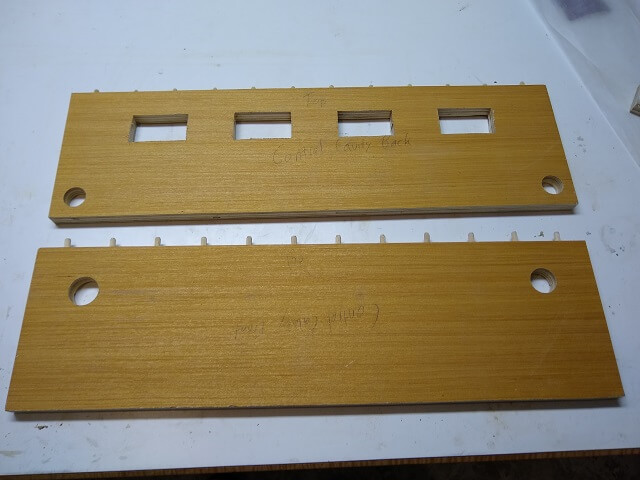
These plates are designed to be used with an electrical box, but I don't really have a need for a box on the other side of the cabinet. So I just have to cut some holes to give me access to the back side of the wall plates. I did this using my scroll saw, which allows "inside" cuts to be made. I could have used my jigsaw as well, but I have a scroll saw available and it's generally more accurate. That being said, while I tried to follow my lines I didn't get all upset if I drifted a bit. These are crude holes and they don't have to be perfect. And they actually turned out a little cruder than I intended. Oh well.
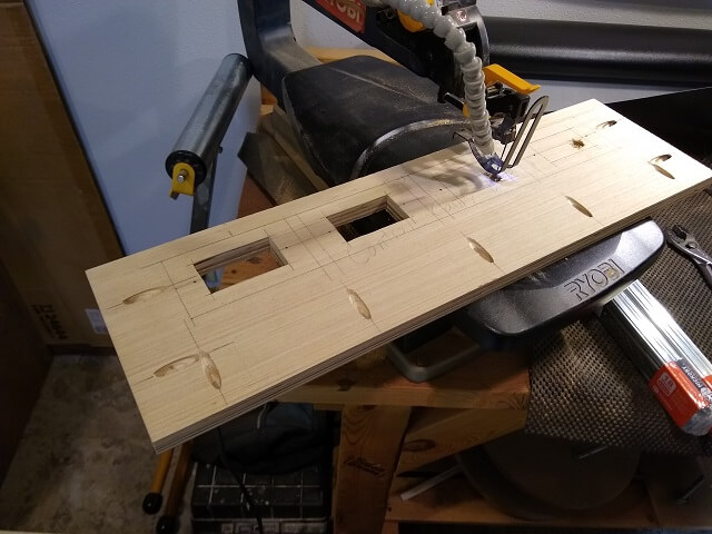
Here are all four of the holes for the access plates. The plates I purchased each support two RJ45 connections, so I will have a total of eight available, which should be more than enough. I calculated I need only four (player 1 joystick, player 2 joystick, player 1 buttons, player 2 buttons), so I have plenty of room for expansion down the road if the need arises.
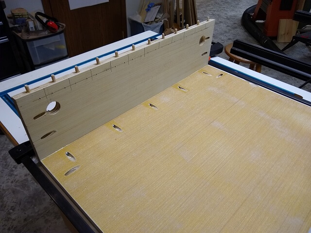
The modular control panels will be held in place with dowels. Holes for these dowels needed to be drilled on the top angled edge of the control panel cavity ends. These holes needed to be drilled as accurately as possible, so it began with careful marking of where they should be located. The dowels will be 2" apart, but placed on the odd number locations (1", 3", 5", etc.) I had to mark this twice, because the first time I did the intuitive thing and marked them at the even number locations. Thankfully I realized my mistake before drilling and was able to erase my lines and start over.
The ends of the boards where the dowels will be installed were cut at an 83.5° angle. My drill press normally drills at a 90° angle. So I had to figure out how to drill these holes into the angled edge. Using a tall fence, I played around with some different size pieces of scrap wood until I found one that when placed at the fence bottom it oriented the angled edge 90° to the drill bit (probably wasn't exactly 90° but it was close enough to work.) Hopefully the picture explains what I did better than my words:
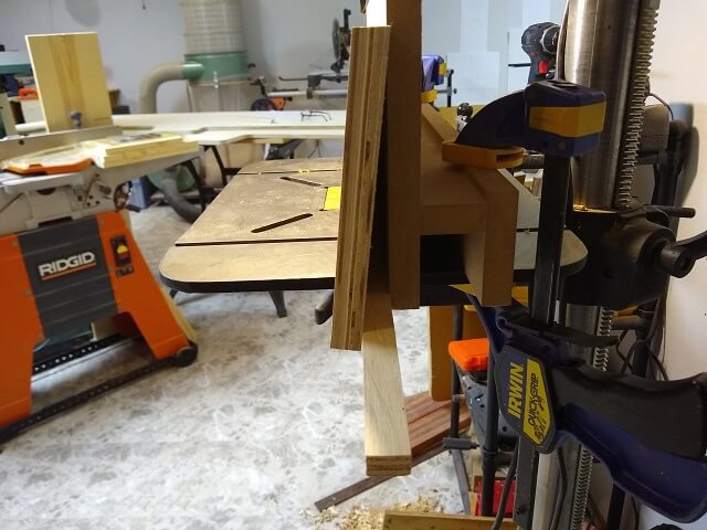
The scrap wood took care of the angle, and the fence took care of the Y axis, so it was just a matter of lining up the drill bit horizontally with the lines I had marked. I set the drill press depth to 1/2" because I'm using 1" dowels.
As I've learned in the past, it is extremely difficult when drilling holes on the edge of a workpiece to get them accurate. And it's rarely an issue with my horizontal position that I do by eye; usually it's the vertical position that drifts which I still haven't figured out because one would think the fence would keep that location dead-on? Despite my best efforts, I had about six holes that were inaccurate. I filled those holes with wood glue and a dowel, then cut the dowel flush.
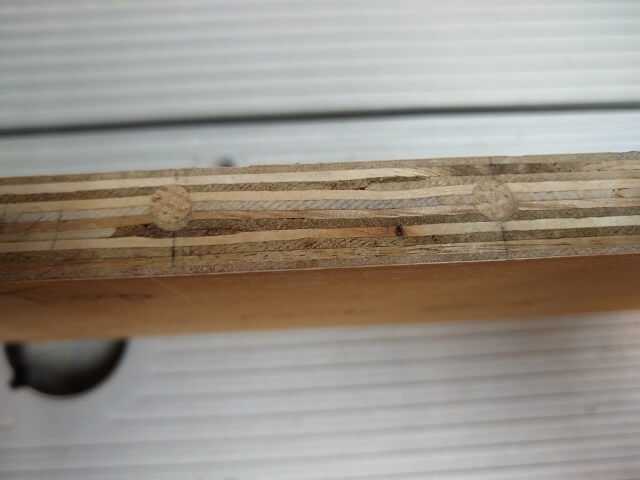
After the glue dried on those hole plugs, I re-drilled them. The final dowel holes weren't perfect, but they were better than the first attempts. They wound up close enough that I could tweak things later to make them work. I glued the 24 dowels in place. Oh, and if you're wondering what's in the can, it's sparkling water.
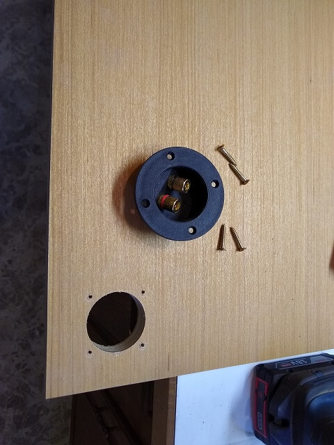
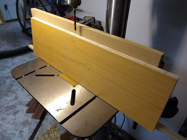
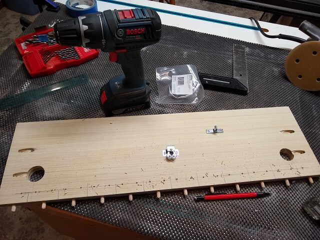
On the front of the arcade cabinet I wanted a button on the right side that will act as the plunger button for when I'm playing Visual Pinball, so I drilled a 1 1/8" hole. On the other side, I decided to put in a USB port. Although I don't have immediate plans, I thought it would be an easy way to plug in additional handheld controls if needed (i.e. to add two more players to the game.) It also would give me an easy place to plug in a USB thumb drive or other accessory without having to unscrew the back panel. (As a side note, after the cabinet was finished I discovered I use these ports frequently, so I'm glad I made the decision to put them in.)
On the rear of the control panel, I drilled two holes on each lower side that will let me pass the wires through to the back.
On the website where I received the inspiration for the modular control system, the author noted that the joystick controls would occasionally have the tendency to want to lift up when in heavy use. All other controls receive only downward force while in use, so it was just the joysticks that had this issue. His solution (and one that I copied) was to put cabinet roller catches on these modular panels.
I drilled holes for the female half of the catch centered between each dowel. The joystick modules will only use one male part of the catch, but by having catches available everywhere it will allow me to place a joystick module in any position.
Later on, when the cabinet was complete, I noticed the panels fit snug enough that they didn't have any problems with lifting. In fact, sometimes I needed to use a little persuasion to get them loose. I wound up not installing the catches after all. But the holes are drilled should I ever want to add them down the road.
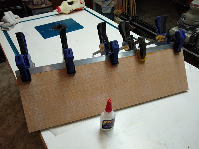
After grain filling and sanding the panel pieces, it was time to connect them. First, I glued and screwed the front of the panel to the bottom.
The panel back was a little trickier, as it was getting mounted in the middle of the panel rather than an edge (a "T" joint instead of an "L" joint.) Thankfully I have some right angle clamps that I used to position the back piece in the right location, then hold everything in place while I installed the pocket screws.
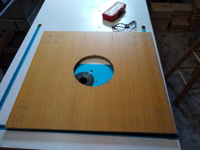
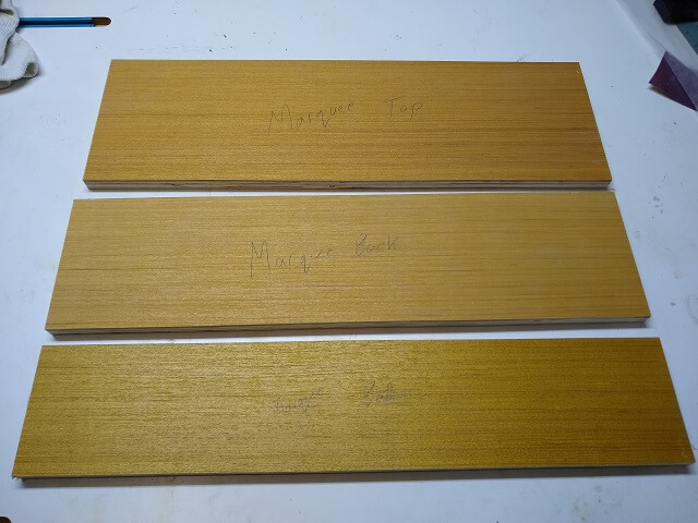
The top of the cabinet will have a nice graphical marquee that lights up just like a real arcade cabinet. Because I'm no artist, I hired out the graphics to GameOnGrafix who did a great job. They made the custom graphic along with two pieces of plexiglass (front and rear) cut to the same size for about $40. The plexiglass would have cost me at least $15 if I were to buy some by itself, so I thought it was a pretty good deal overall. And it looks way better than anything I would have made on my own:
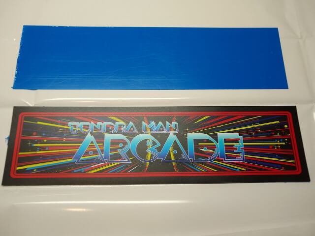
By the way, the blue rectangle in the above photo is the plexiglass pieces. They still have the protective film on them, so that's why they're blue.
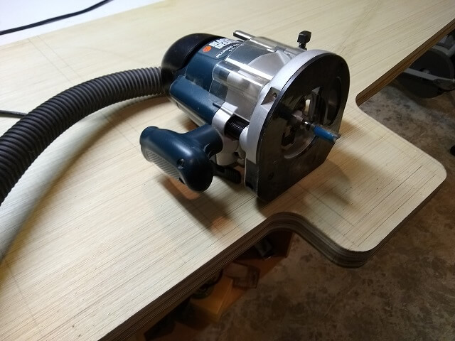
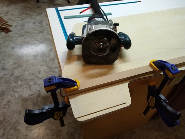
The two sides of the marquee glass will be held in place by slots in the cabinet sides. The plexiglass pieces were 1/16" thick each, plus the slight thickness of the graphic card. I also wanted a little extra width to the slots so the pieces could slide in and out without being overly tight.
I chucked up a 1/8" bit in the router, and then measured where to clamp a straightedge that I could run the router against. I then made a pass at 1/4" deep. To widen the slot slightly I just nudged the straightedge over a hair and made another pass. I did this a couple times until the two pieces of marquee glass sandwiched with the graphic panel would slide in and out easily.
I then had to re-do the above step on the other side of the cabinet, but I didn't get a picture of that. Imagine the same thing, only the mirror image.
The assembly that will make up the marquee section is composed of three pieces: a bottom, a top and a back. The bottom and back will be permanently affixed to the cabinet sides. The top will be removable so I can install/remove the marquee graphic and service the light fixture. Because it needed to be removable, I cut the top piece about 3/32" narrower than the other two pieces. This will give me a little wiggle room without having to wedge the top piece tightly into place (and then scratch my head when I want to figure out how to remove it later.)
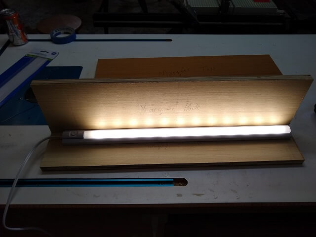
Speaking of the light fixture (and I was), I bought a plain old 24" under cabinet LED light. It was rated at 432 lumens so hopefully this will produce sufficient light for the small marquee area. I guess if it turns out to be too dim, it shouldn't be major surgery to replace it down the road. Once installed in the cabinet I plan to line the inside of this area with foil tape to make the area reflective and hopefully push more light out through the marquee. Also note that in this photo the light is just laying face-up on the pieces. Once installed it will be on the back wall facing straight out.
I drilled the pocket screw holes in all the pieces, and also drilled a hole to pass through the electrical plug for the light. Because it was easier to do it now, I went ahead and drilled the holes for the screws that will mount the light fixture as well.
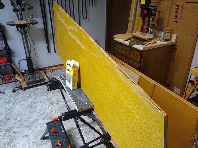
I've taken care in designing my cabinet so that no plywood edge will be showing. The cabinet sides will have the edges covered in T-molding, and I was able to arrange panels to hide most of the remainder of the edges. One area that would be the exception would be the top and bottom of the marquee where the horizontal plywood pieces would have their ends exposed.
Unfortunately, next to the screen, this probably will be the most looked-at part of the cabinet. I thought about trying to pack the plywood ends with filler but feared that the laminates would still telegraph through the paint. I also considered gluing on some solid wood pieces, but decided that would be a lot of hassle.
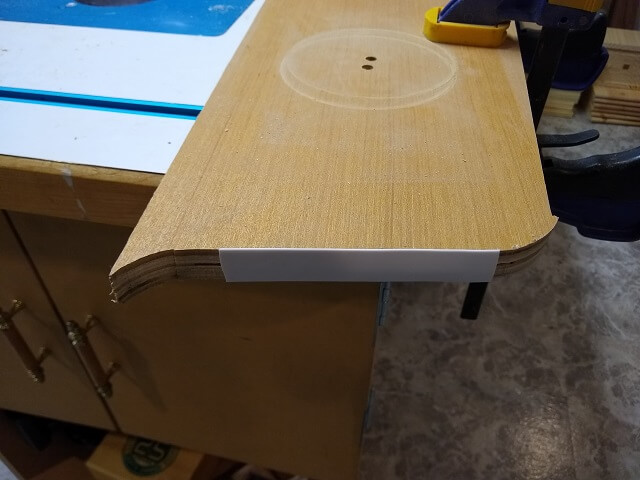
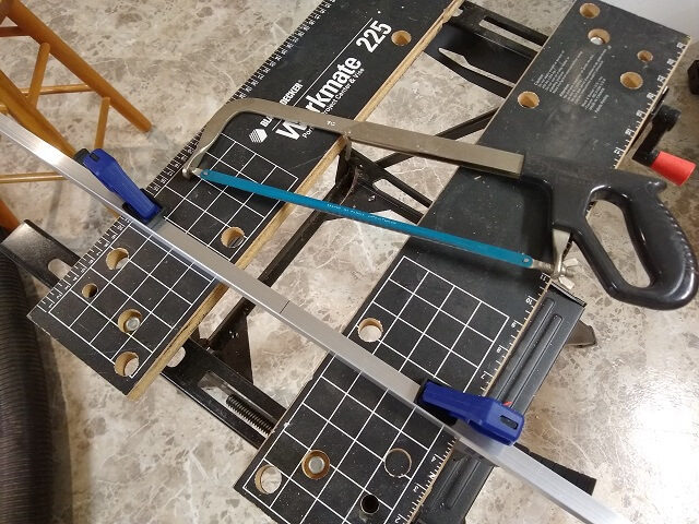
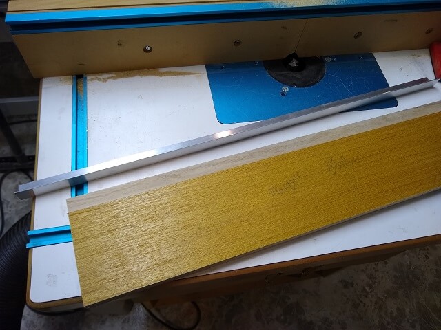
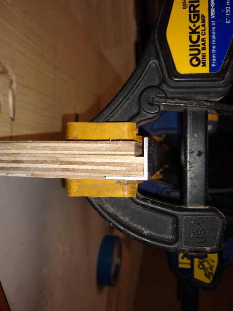
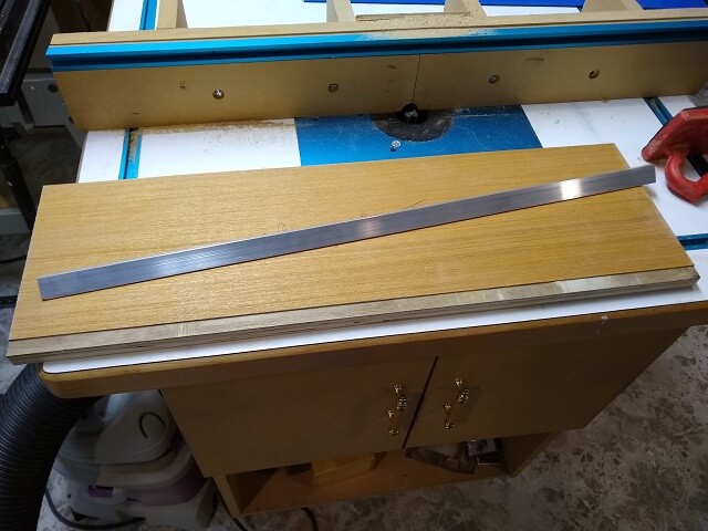
Instead, I bought some aluminum "L" channel from the home center. This will serve multiple purposes: it will smoothly hide the ends of the plywood, and it will also serve to hold the top and bottom of the marquee glass in place. I needed two 24" pieces, and thankfully was able to find a piece at the home center that was 48 1/8" which would give me room for the kerf once it was cut in half.
I marked the halfway point and then broke out my hacksaw and cut the pieces in two. Unfortunately, hacksaws aren't a real precision tool. My cut was visibly out-of-square. Luckily there was enough extra length that I was able to use my disc sander to bring the ends perfectly true, and also slowly grind the channel to the perfect length.
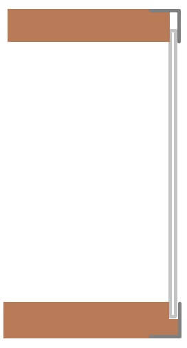
Trying to explain with words how the plywood, aluminum and plexiglass will all fit together is difficult, so in the spirit of "a picture is worth 1,000 words" I sketched up the side profile. The brown pieces are the wood. The light gray is the plexiglass, and the dark gray is the aluminum.
The bottom piece will have a little "shelf" that will hold the marquee glass at the proper height, while the aluminum channel will keep the glass from falling out the front. Similarly, the top aluminum strip will also keep the plexiglass from falling out, but because of gravity we don't need a "shelf" on the top.
And rather than having a bit of a bump where the aluminum sits on the wood, I planned to rout a recess for it to sit in. This should look clean and professional once all painted up.
I started by routing the "shelf" on the bottom of the marquee. This will allow the plexiglass to sit 1/4" lower than the top of the plywood. Like the slots I routed earlier in the cabinet sides, this shelf was sized slightly wider than the plexiglass to allow the glass to slide in and out without binding.
Here is the finished "shelf" after routing. It's kind of hard to see because plywood tends to make everything in the pictures run together.
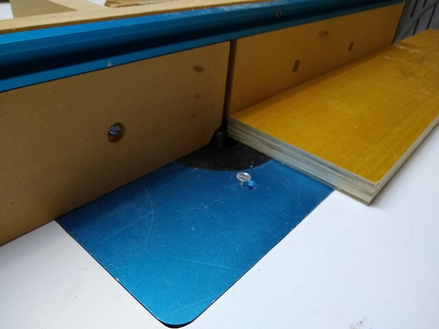
Then I flipped the bottom over and routed the recess for the aluminum L channel.
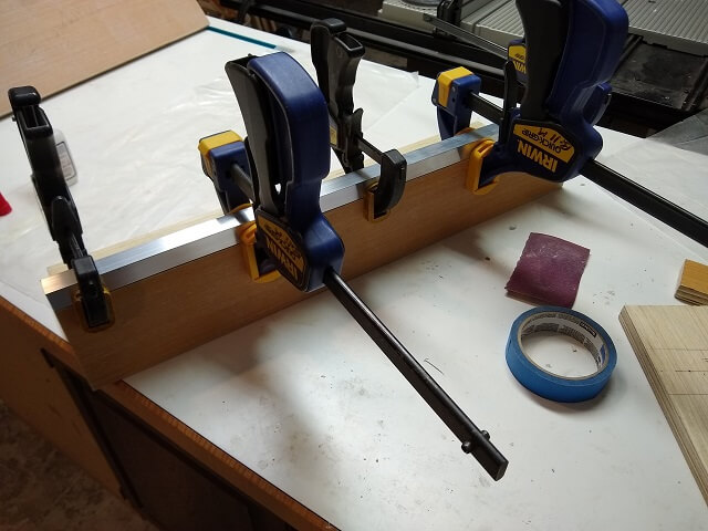
So here is the L channel clamped in place so you can better see the real McCoy.
Using the same router settings, a recess was also cut in the top piece to hold that aluminum.
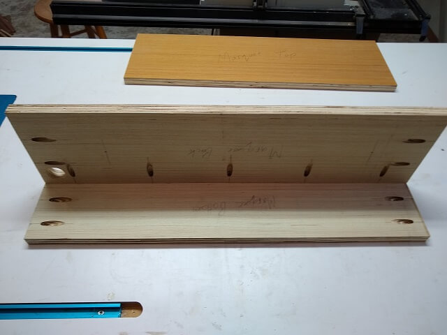
With the routing done, I attached the marquee back to the bottom piece with glue and screws. As I mentioned earlier, the top won't be permanently affixed to this assembly.
I wanted something a little visually cleaner than screws to hold the aluminum to the wood. Screws would have worked fine, but I decided with this design I should never need to take it apart, so super glue would be a better option. This way the edges of the aluminum would be perfectly smooth and square.
Likewise, I glued the other piece of channel to the bottom assembly. I should also mention that I wiped both the aluminum and plywood down with naptha just to make sure there wasn't any oils or other dirt that might cause issues with the glue adhering.
Click here to see me build various other pieces of the cabinet.
Return To The Main Wood Gallery
This page last updated on 01/04/2024