


Lots of other little pieces needed to be build before they were attached to the main cabinet. Here's the page where I talk about those.
Above the player control panel where the joysticks, fire buttons, trackball, etc will be located, and directly below the monitor, will be an upper control panel. This panel will contain the buttons to add "coins", start games, pause, system power and access admin functions. In addition this panel will hold the audio controls.
Many builders I've seen will either change the volume by a knob hidden somewhere inside the cabinet, or by using a mouse and adjusting the Windows/operating system audio volume. I didn't like either of those methods, as if I started a particular game and it was too loud or soft I wanted to be able to quickly adjust things without jumping through hoops.
I know having the audio controls available to the user departs from the traditional arcade cabinet. Players back in the day didn't have the ability to decide they wanted Congo Bongo at twice the normal volume. However, they also didn't have access to a power button either. Or buttons to add free quarters for that matter. So making the audio controls easily available is a concession of convenience over authenticity. I'm not trying to replicate an arcade game down to every last detail so I'm not going to lose any sleep over it.
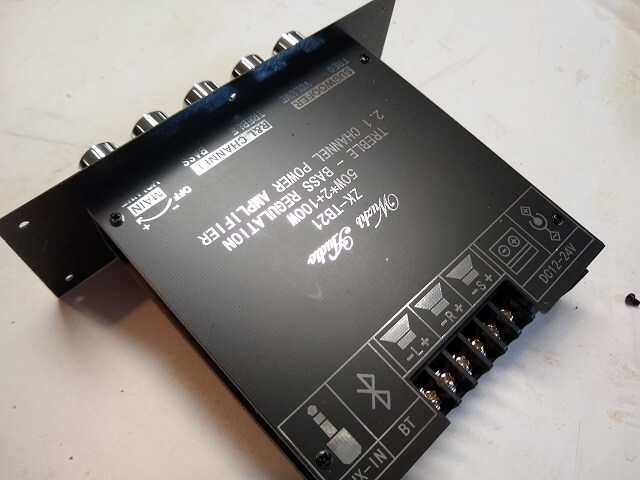
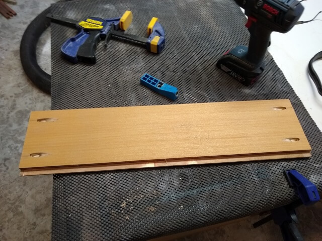
For an amplifier, I purchased a small solid state 2+1 amp. It came as a raw circuit board, with a couple of metal covers that could be screwed on the top and the bottom. The knobs on the front, however, were just pressed onto visible potentiometerss soldered to the PCB board with no face plate.
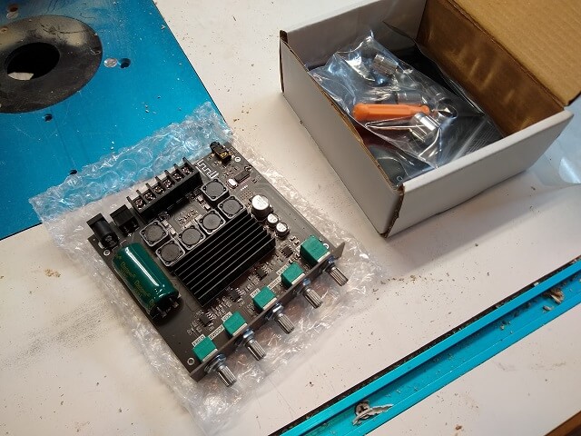
Because I wanted a relatively nice looking interface to the audio controls, I was going to have to do something to pretty it up. The first thing that came to mind was to drill holes in the plywood where it will be mounted in order for the potentiometers to pass through. However, the pots were only about 1/2" long which obviously wouldn't protrude through a 3/4" piece of plywood.
So, I took a page from my guitar building experience and decided to build a bezel out of thin plastic. The amp could be mounted to this bezel, then the bezel itself could be mounted to the panel. For you guitar players in the audience, I'm basically going to make a pickguard like what would hold the controls on a stratocaster.
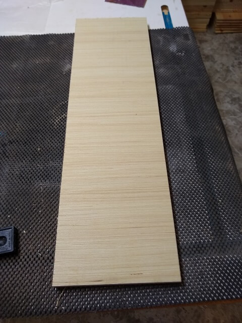
I began by looking at my pile of plastic stock and finding a scrap piece of plain black plastic that was the right size. I then cut a piece of scrap plywood to the size I wanted for the bezel and attached the plastic with some double-sided tape. Note that the piece of plastic has a protective film across the top to keep it from getting scratched up while shaping it, so it will look a lot better in a few minutes.
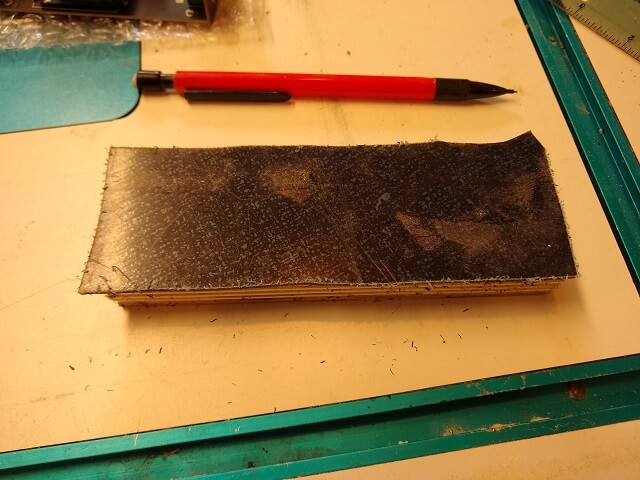
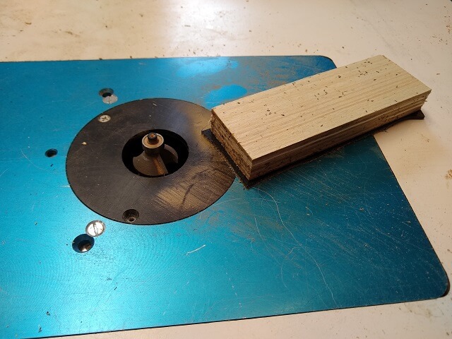
Because the block of wood is the desired size, I could use a flush-trim router bit to make the plastic the exact same size. A plain square edge isn't all that visually appealing, so I wanted to put a 45° bevel around the edge. Instead of using a flush trim bit I used a beveling bit with a bearing. This cut the plastic piece to size and fancied up the edge at the same time.
Plastic routs very easily, but it does throw plastic chips everywhere in the shop. It doesn't seem to matter how much dust collection I use. These chips are larger than typical sawdust chips, and as a bonus get charged with static so they cling to everything they hit.
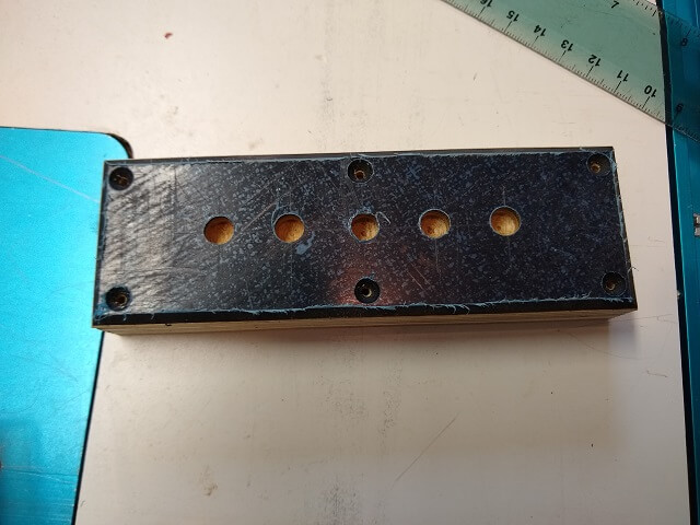
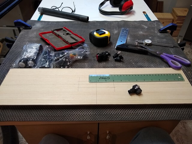
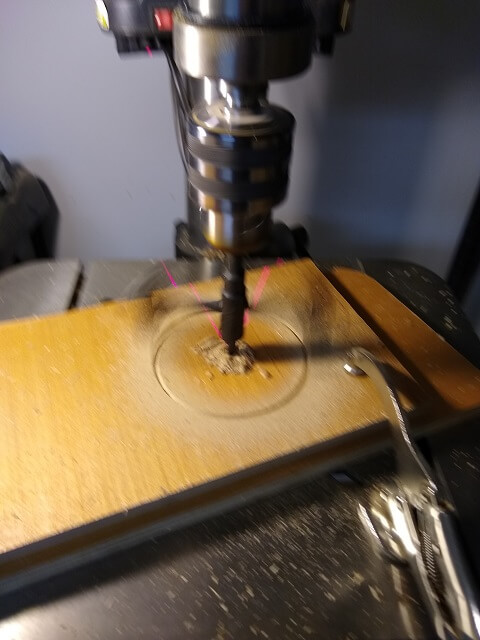
Now the holes for the pots needed to be drilled in the plastic bezel. There are five pots on this amp (subwoofer crossover frequency, subwoofer volume, bass, treble, and master volume.) Of all the odd measurements, they were spaced 18.5 mm apart. Because of this I had to very carefully mark where the holes should be drilled. My laser pointer on the drill press really helped get the holes drilled right on my marks.
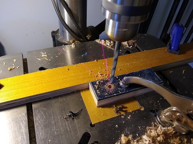
Next, holes for the bezel mounting screws needed to be drilled. Rather than just having screw heads sticking out above the face of the panel, I used a countersinking bit to put a nice recess on each screw hole. You can countersink with a hand drill, but using a drill press allows each one to be the exact same depth.
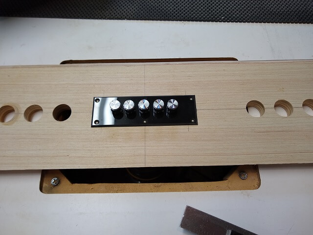
With the plate done I was able to remove the protective film and mount the amp. Thankfully my hole spacing lined up perfectly.
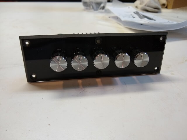
The last thing for the amplifier assembly was to mount the top and bottom cover. Mostly these covers just protect the amp from having something metal come in contact with the raw board and shorting it out. Once the amp is mounted in the cabinet nobody but me will see these covers.
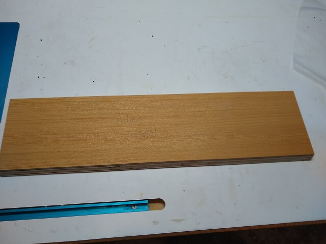
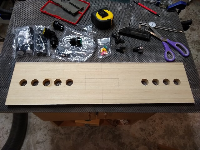
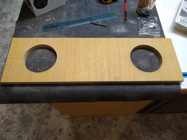
With the audio panel done I needed somewhere to mount it. I cut a piece of plywood 24" wide and 6" tall.
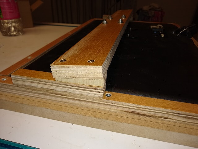
The top of this panel will also be what the monitor bezel rests upon. To give it a nice look, I routed a channel on the back side. The monitor bezel will eventually slide down slighty behind the top edge of this control panel.
On the back side the holes for the pocket screws were drilled. I kept them close to the edges because I needed room for the buttons in the middle.
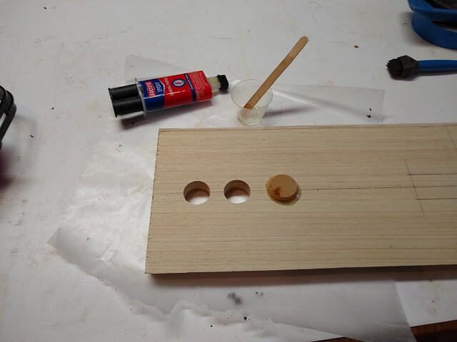
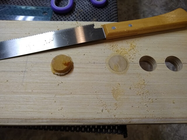
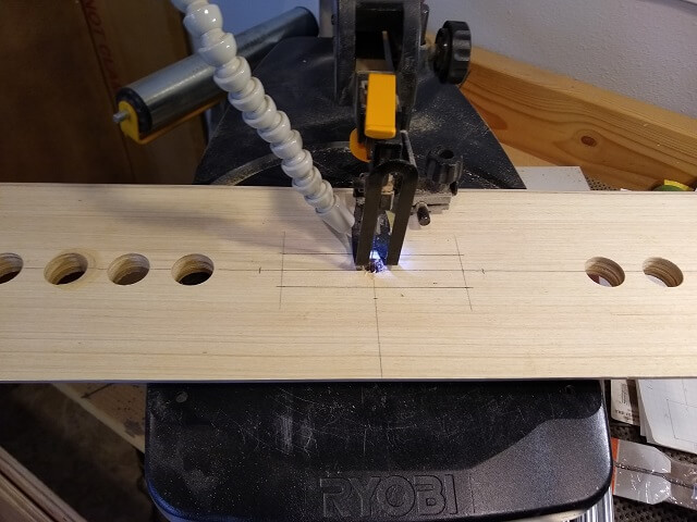
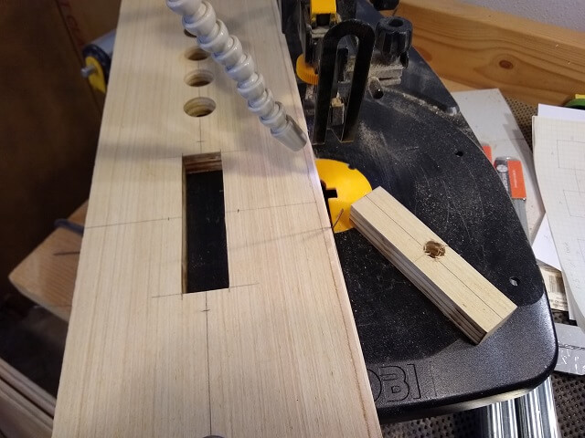
I had nine total buttons that needed to be mounted in addition to the audio panel. The buttons being used on this panel are LED lighted and require a 1" hole. I did a lot of careful (so I thought) measuring to figure out where things should go.
I then started drilling the holes for the buttons. Oops. After I drilled the third hole I immediately noticed that the spacing was off compared to the previous two. I'm pretty sure I drilled right on the mark I had made, so that meant I probably made the mistake when measuring out the places to drill. It was off about 1/8". While that may not seem like much, in a row of equally spaced buttons a gap like that will be painfully obvious.
So at this point my choices were to start over with this panel, or figure out a way to fix it. I decided to try and fix it. One advantage to painting the project with an opaque color is that it gives a lot more options for fixing mistakes like this. In the case of this piece, I'm going to be covering it in vinyl so that's even more concealing than paint. If I was going to stain and/or put a clear finish over this cabinet so that the grain was visible there was likely no way to fix my mistake without it being visible.
Thankfully the goof is fixable. This conveniently was a 1" hole, so I cut a short piece of 1" dowel to use as a plug. I then mixed up some five minute epoxy and glued the dowel in place. Normally I like to use 60 minute epoxy because it's stronger, but in this case the repair won't be structural and using the quick stuff will get me back to work sooner.
I know the package says "5 minute epoxy." That means the epoxy kicks in five minutes. "Kicks" is a term used to mean that the chemical curing process starts. Five minute epoxy means you have about five minutes of open time as soon as the resin and the catylist touch each other. After mixing well for a couple of minutes you don't have much time to get the glue spread and the pieces in place. Then, despite what the package would lead you to believe, it takes at least an hour for the epoxy to reach full strength.
A few hours later after the epoxy had dried (ok, "cured" for you pedantic types) I grabbed a flush cut saw and trimmed off most of the excess dowel. It wasn't perfectly smooth, but it was good enough that I could re-mark and re-drill the hole in the correct spot.
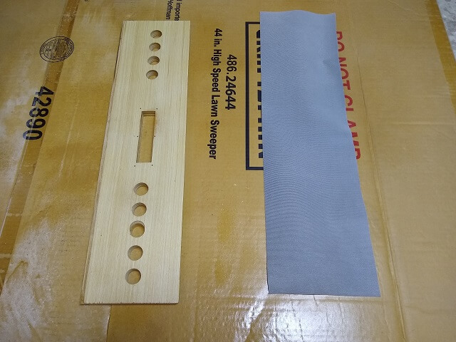
And once it was sanded my panel was repaired. You can see the "half moon" of the dowel filling in the space of the old hole, so it's pretty obvious how far off my first attempt turned out. Once the vinyl is applied this repair will never be seen again.
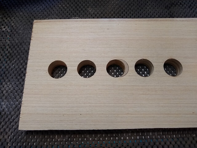
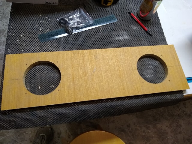
Here is the panel with all nine holes drilled. Because there is an odd number of buttons I had to put four on one side and five on the other. Rather than centering the four buttons on the right side, I used the same spacing as the left side. This gave me an additional spot if I ever wanted to add another button.
The hole for the audio amplifier was next to be cut out. I did this using my scroll saw which has the ability to do "inside" cuts.
The nice thing about the scroll saw is it makes an extremely smooth cut that doesn't require any sanding. There is a bit of a learning curve to figure out how to make straight cuts and sharp corners, but with some practice it's a very useful tool.
With the hole cut out, I placed the audio panel in place and marked and drilled the holes for the mounting screws. That pretty much wrapped up the construction portion of this panel.
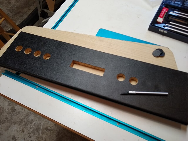
Because the panel was going to be a "high touch" area, I didn't want to just paint it. Paint wouldn't provide a nice tactile feel, and would quickly wear away. I opted to cover the panel in vinyl, which is the same material I am using to cover all the modular control sections.
I was going to use spray adhesive to adhere the vinyl to the wooden panel. A section of the vinyl slightly larger than the panel was cut out, and I placed this face-down on a large piece of cardboard along with the control panel. Following the instructions on the glue can, I gave each piece a medium coat of glue and then let them sit for a minute before sticking the two together.
This mostly worked. The control panel had a curved edge that the vinyl had to be wrapped around. I held the vinyl in place around this curve until the glue had a chance to set. However, it seemed like the vinyl would peel away from the wood with less effort than I was hoping. I was worried that over time the glue would slowly release and the vinyl would start to pull away from the panel, especially around the curved area.
I decided to try going around the edges of the vinyl with thin super glue, and letting the fabric backing "wick" the glue under the edge. This actually worked pretty well. When the super glue dried the vinyl felt pretty secure to the wood and no longer wanted to peel away with minimal force.
After the glue had dried I spent a few minutes with an X-Acto knife and neatly trimmed the vinyl even with the edges of the panel. This included removing the material covering the audio panel opening, and the button holes.
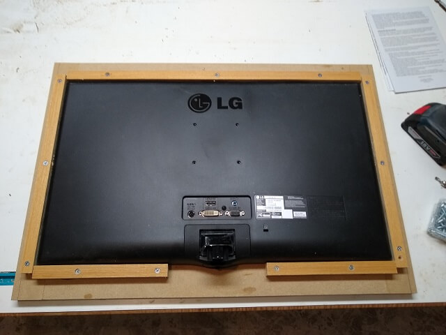
The monitor in my cabinet is going to be a plain old 24" LED computer monitor. However, I didn't want it to be completely obvious that I was using a computer monitor, so I decided to build a bezel to surround the screen. This bezel would be just slightly wider and taller than the visible screen area, and hide the monitor edges and manufacturer's label.
Now the simplest solution would seem to be to just take a sheet of plywood the size of the bezel and then cut a hole in it. However, pulling this off becomes problematic. First off, it is very difficult to get the hole centered exactly in the bezel. It might be close, but it won't be exact. Unfortunately, this is the lesser of the two problems.
Second, given that this is an inside cut limits what tools one can use to remove the center area, and of the tools that remain (jig saw, scroll saw, coping saw, etc.) it is nearly impossible to make a perfectly straight cut. It may look nice and straight when staring at it by itself, but once it's placed next to the perfectly straight edge of the monitor screen, all of the little variances will become painfully obvious.
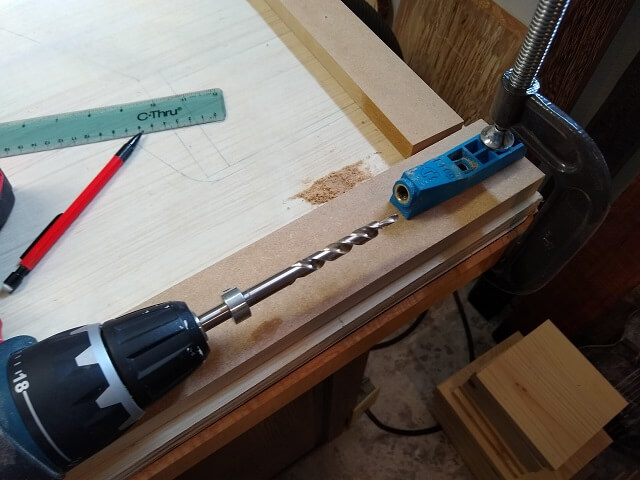
Thankfully there's a simple way to make a perfectly centered and square bezel: rails and stiles. By doing a little bit of simple math, one can cut four pieces of wood that are then attached to each other to make a frame. As long as the pieces are cut to the proper length and width, the bezel will turn out perfect.
Because I was going to be chamfering the inside edge of the bezel, I opted to use MDF. Chamfering plywood would have left some laminated edge visible and it would take a lot of wood filling and sanding to hide it. MDF doesn't have this issue.
Unfortunately MDF also isn't as strong when glued and/or screwed together, but because this bezel isn't structural I decided it was probably strong enough.
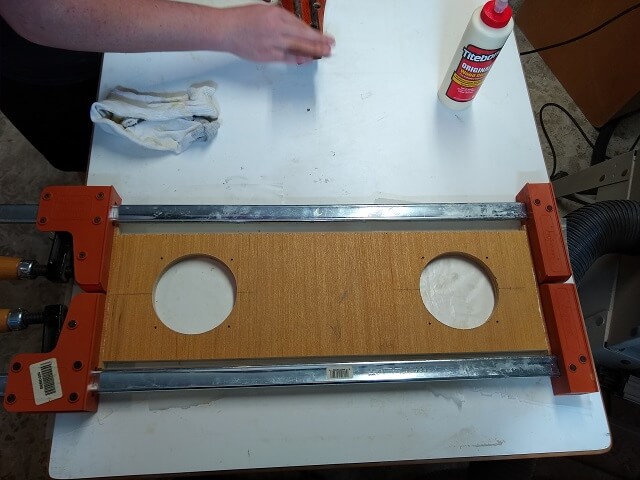
I was planning on gluing the pieces together. However, to increase the strength (especially while the glue dries) I also decided to add some pocket screws to the back side of the bezel where they would never be seen.
One trick I've learned that greatly increases the strength of MDF glue joints is to apply a thin layer of glue to the surfaces to be joined, and then let the glue dry completely. This seals the MDF so the next layer of glue doesn't get absorbed into the wood and does a better job of holding the pieces together. One demonstration I watched showed that it doubled the strength of an MDF glue joint. A double strength MDF glue joint isn't strong, but it's strong enough for what I'm doing.
So I glued the rails and stiles together, then used the pocket screws to draw the pieces tight while the glue dries. In holding the frame up against my monitor it was perfectly straight and square.
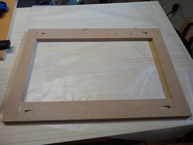
Once the glue was dry I could bevel the inside edge of the bezel at a 45° angle. I did this by chucking a chamfering bit into my router, and then running the inside of the bezel around the spinning bit. I did this in a couple passes, raising the bit each time until it reached final height. MDF doesn't have the chip-out risk of other woods, but I figured it was easier on my router if I didn't take a whole ton of wood off at once.
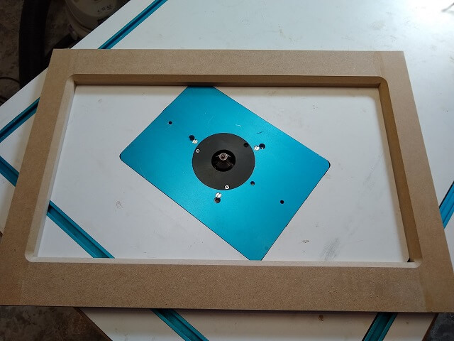
Here is the bezel after the routing was done and I flipped it over. The corners are rounded due to the round bit, but I think it actually looks good that way. The beveled edge of the bezel will make it look better (less "blocky") and also will fool the eye to make the monitor look a little bigger.
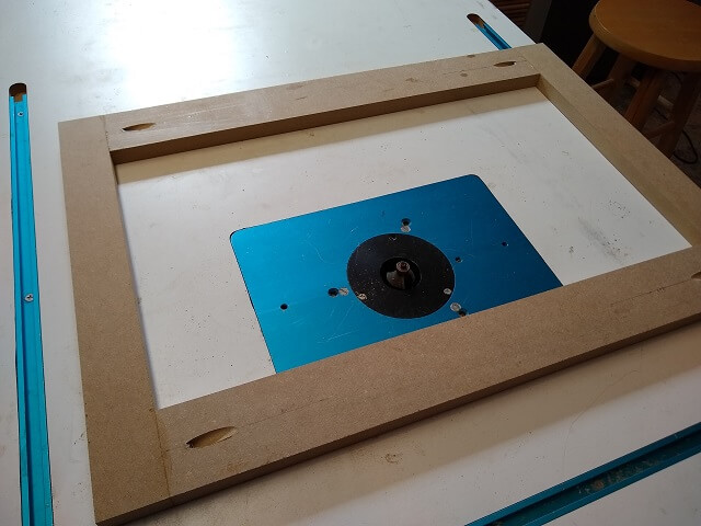
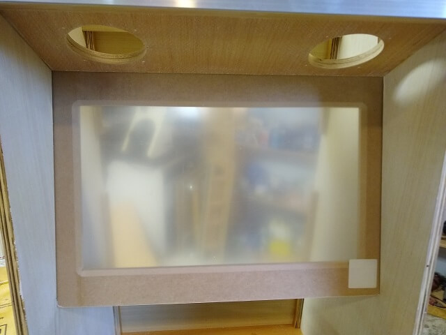
The monitor itself will be suspended by a VESA mount. One of the things that concerned me, though, was how to keep the monitor completely centered in the bezel. The chances of getting the mount positioned exactly perfectly were low. It would likely be off a mm or so in one or possibly two directions. And because I designed the bezel to surround the screen so closely any small variation would be quite noticeable.
After pondering a few various (and overly complicated) solutions, I finally had the epiphany to add some cleats to the back of the bezel to hold the monitor in the correct place horizontally and vertically. These cleats will not support the weight of the monitor, they're just used to keep the monitor front in the right spot. Easy peasy.
On the front side of the bezel, a piece of plexiglass was going to separate the user from the LED screen. A sheet of plexiglass was easily available from the home center, but it came in a larger piece than what was needed for this application. Years ago (like 20 years ago) I had bought a plexiglass cutter for another project, so I pulled it out of the tool drawer and put it to use.
More or less the plexiglass cutter is like a utility knife with a hooked blade. I made about 10 scoring passes with the knife in the proper location, then flipped the plexiglass over and made 10 more passes on the opposite side. With the plexiglass scored, I could apply pressure and "break" the glass to size. The score lines ensured the edges were nice and clean.
Once the plexiglass was cut to the same size as the bezel, I could test fit the two pieces in the cabinet. There was just a little bit of wiggle in the slot that holds the plexiglass and bezel, and this can easily be tightened up using shims once I'm installing everything permanently. The wiggle isn't a bad thing, as if the fit was tight I would never be able to slide the bezel and plexiglass down the slot and into place.
Now focus needed to shift on the system to hold the monitor to the back of the bezel. A piece was cut and holes were drilled for the VESA mount. The VESA mount would be attached to the monitor, then the other side of this mount would be attached to a frame piece to hold everything in place. I suppose the frame piece could have been screwed directly to the back of the monitor without using the VESA mount, but that didn't allow for any wiggle room. Using the VESA mount gave me a little more adjustability.
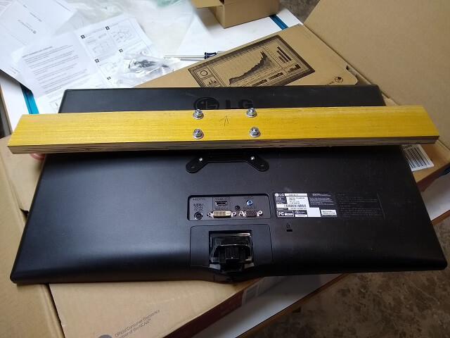
Next, the frame piece with the VESA mount had to be attached to the bezel somehow. This was done using screws. The only tricky part was, there was a lot of clearance between the frame piece and the bezel. I filled most of this space by gluing pieces of scrap plywood to the bezel. The remaining space was a little trickier, as it was thinner than a piece of plywood, and also wasn't square. I did some careful measuring of the thickness and angles needed, then cut some plywood pieces that would fill this gap. These angled pieces were attached to the back of the frame piece. Then screws were used to connect everything together. I didn't use glue as these pieces need to come apart when installing/removing the monitor from the bezel.
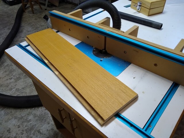
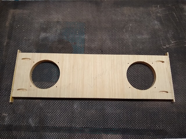
The speaker panel will reside at an angle above the monitor and below the marquee. I purchased some 5 1/4" car stereo speakers that should more than do the job.
To start, I cut a panel 24" wide by 7 1/16" long. You can't really see it in this picture, but one side of the panel is cut at a 79° angle. This is the side that will meet up with the monitor bezel slot. Leaving the edge of the board at a right angle would have caused a little bit of the piece to hang over the edge of the channel which would interfere with the monitor bezel sliding in and out.
Nearly 20 years ago I made nine mission style clocks which I gave out as Christmas presents. These clocks required a perfectly round hole for the clock face, much larger than a standard drill bit could make. Cutting the hole with a saw wouldn't be precise enough. So, at that time I bought a circle cutter.
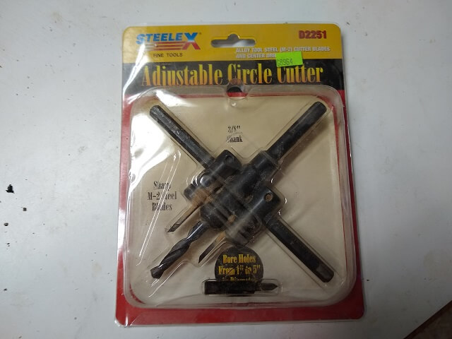
That circle cutter has pretty much sat unused since that time. Seeing as I had the tool in my possession, why not use it to cut out the speaker holes? I don't think I would have bought this circle cutter just for this purpose, but I might as well use it if it was already available.
The holes for the speakers needed to be 4 1/2" in diameter. I set up the blades on the cutter to the proper size. I also dropped my drill press speed to 250 rpm. Large diameter cutters like this one can become dangerous with high drill speeds. Also, I feel like I shouldn't need to say this, but never use a circle cutter in a hand drill. Unless, of course, you enjoy traumatic injury.
Because I'm a nerd I did a little math and figured out that a 4.5" diameter cutter turning at 250 rpm works out to the cutter edge moving at 3.35 mph. That doesn't seem that fast on paper, but once you see the cutter in use it looks like it's really flying.
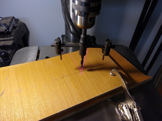
With the drill press running, it was just a matter of slowly lowering the bit until I was all the way through the wood. I would often pull the bit out to let it cool down, as I could feel the heat coming off the cutting edges. Once I was getting almost all the way through the bit started making a lot more noise. Not sure what that was about.
I cut out both holes. It's almost a shame that they will be covered with speakers because the holes looked pretty nice.
The last thing I had to do was drill the holes for the screws that will mount the speakers.
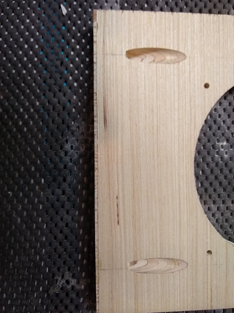
I thought I was done with the speaker panel. Then at some point I noticed that early on I had grabbed the wrong piece of plywood, and that my speaker panel was only 23 7/8" wide (it needed to be 24".) Bummer. I thought about just making a new panel, but that seemed like too much work. Instead I decided to just glue some additional material onto each side of the panel to make it wide enough. The easy way would have been just to add the material on one side, but then my speaker holes would be slightly off center. Maybe nobody but me would notice, but me noticing was enough. I glued an 1/8" strip of plywood onto either end of the panel. This will make the panel too wide, but I can trim it to size later.
After the glue was dried, I took my flush trim saw and cut off the extra tabs sticking out on the edges so the newly glued pieces were the same width as the speaker panel. Then I used the table saw to take just a little bit of width off each side until the panel was the exact width needed. Once sanded and painted, nobody will ever know a mistake was made.
Here is a close-up of one of the strips after it had been fully trimmed to size. You can see that it is now only about 1/16" wide. The other side has been trimmed to the same size, but I didn't get a picture so you'll have to take my word on it. The speaker panel has now been widened and the cutouts are still perfectly centered.
When I say "electrical panel", what I'm making in this section is not what immediately comes to mind. On the lower back side of the cabinet I'm going to have a panel to enclose the back. This panel will also include the power cord jack plate. Hence, I'm calling it the electrical panel to differentiate it from the other panels.
The easy way to get power to the cabinet would be to just drill a hole and run an extension cord out the back. I don't always do things the easy way. Also, I wanted the back to look clean and professional as much as the front. So I decided to use a standard C14 power cord jack plate.
I initially ordered one that was just the jack, without a power switch which I don't really need. Unfortunately, that item went out of stock right after I placed the order and they didn't know when they would be getting more. So I looked around and could only find plates in stock that had a power switch. So I'll now have a power switch on the back of the cabinet that will likely always stay in the "on" position.
I marked out the hole for the plate. This plate only had about 1/16" of a lip around the edges, so there wasn't much wiggle room if I cut the hole too big. I used my jigsaw to cut the hole. In retrospect, I should have put a different blade in the jigsaw as the resulting cut was pretty hacked up. However, once everything is in place this hole will be hidden and I'll be the only one who knows how ugly it is. Well, me and the entire internet who reads this and sees the picture.
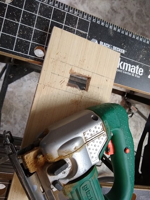
The hole was just a little tight, so I grabbed my rasp and fine tuned it until the plate fit in nice and snug.
The back side of the switch plate will have exposed wires, and potentially could be touched when using the storage cabinet. So to prevent accidental contact with electricity there will be an electrical box covering everything on the inside.
Overall, this panel was pretty simple to make. The last thing I had to do was drill the holes for the pocket screws on the inside. In this picture you can see how bad the jigsaw tore out the backside of the plywood. Thankfully this disaster will be covered up with an electrical box so I'm not going to worry about fixing it.
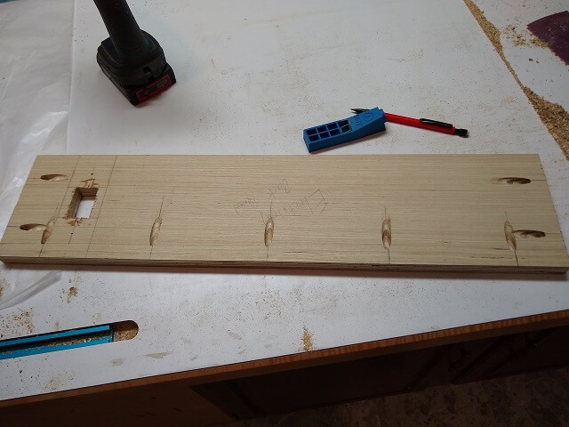
I needed a shelf to hold the PC in the back of the cabinet. Nothing fancy. Just a board with some pocket hole screws to keep it in place.
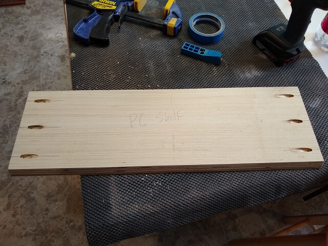
This piece was so simple I probably didn't need to make a section for it. But I took a picture of the thing, so why not include it?
Now it's time to put all these different pieces together. Click here to see the assembly process.
Return To The Main Wood Gallery
This page last updated on 01/04/2024