


At long last it was time to start attaching all these pieces to each other. I had mulled over some different orders of assembly so I could attach everything together, and finally decided that the easiest would be to lay one side of the cabinet on the bench, attach the three larger assemblies, then set the other side of the cabinet on top and fasten it in place. That seemed easier than trying to put the cabinet together in an upright position. Every time I entertained that notion I couldn't figure out how to do it without at least three hands.
First things first, however, I wanted to add some cleats to the bottom for extra support of the subwoofer assembly. The bottom of the subwoofer box would be supporting most of the weight of the cabinet. Seeing as the cabinet was going to be over 200 pounds once finished, I didn't want ten pocket screws to be the only thing supporting all this heft. It probably would have been ok, but I figured a little overkill would help me sleep better at night.
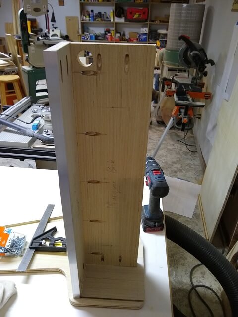
So using wood glue and screws, I added a cleat to the bottom of each cabinet side. The bottom of the subwoofer assembly could then butt up against this cleat which will assist in supporting the weight.
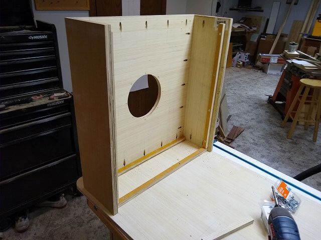
The subwoofer assembly was then glued and screwed into place. You can see the cleat I added in the previous step along the bottom edge of the assembly. Another cleat was added along the top edge that will help support the subwoofer box top, which will be installed later.
I then moved to the other end of the cabinet and glued and screwed the marquee assembly into place. I had to carefully line up the slots for the plexiglass panel so I would have clearance to slide it into place.
Then the control panel assembly was glued and screwed into place.
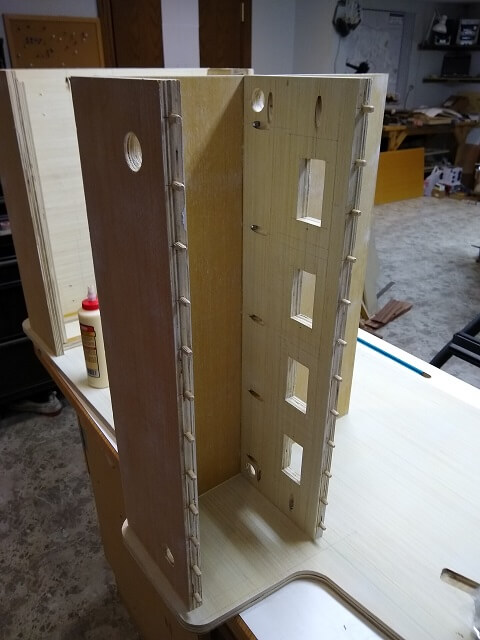
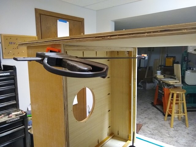
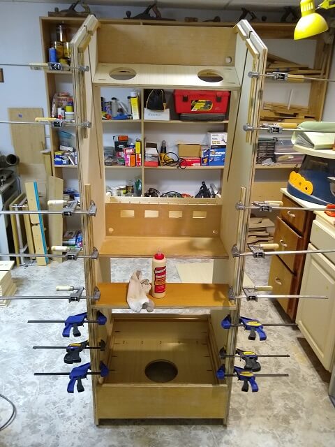
Now I could place the other side of the cabinet on top of everything and fasten it in place. Getting glue on the edges without smearing it everywhere took some care. Once again, I started on the subwoofer side. The clamp in the photo was just used to keep the edges of the subwoofer assembly from splaying out while I was attaching the cabinet side.
Then I worked my way to the other end, first attaching the control panel assembly and finally the marquee assembly.
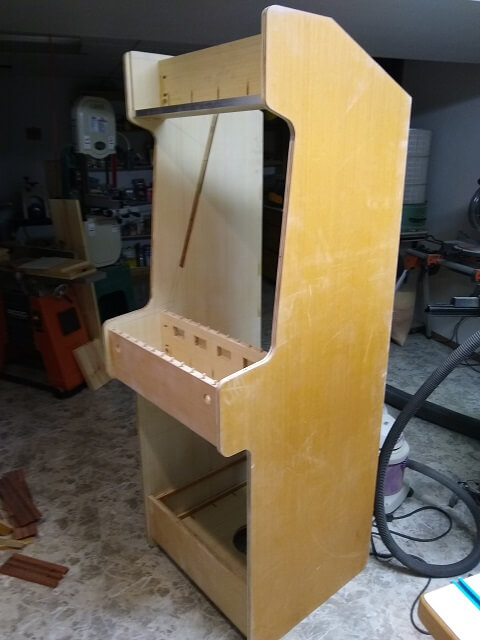
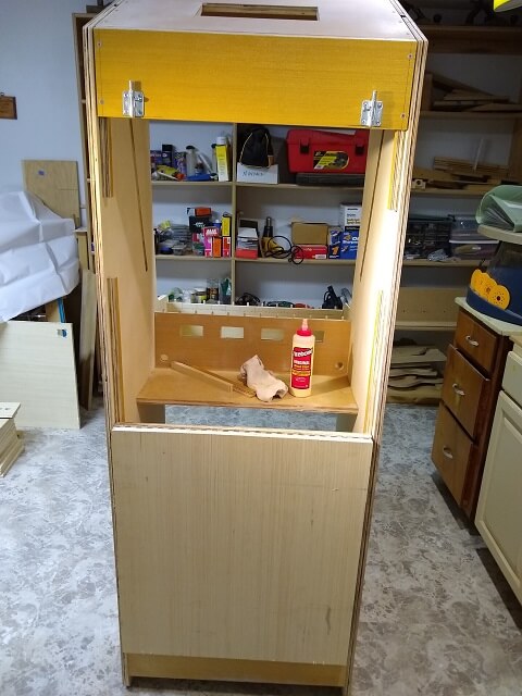
With these three assemblies attached to the side I had a basic structure. I was able to set the cabinet upright and have a look-see. It was pretty cool, and the true size of the cabinet became "real." I'm glad I didn't make it the full depth of an original cabinet (this is 4"-6" shallower,) as that would have been huge. I probably would have been OK to go with my original plans of 24" deep at the control panel (currently it's 28" deep.) But it will work.
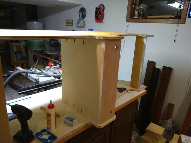
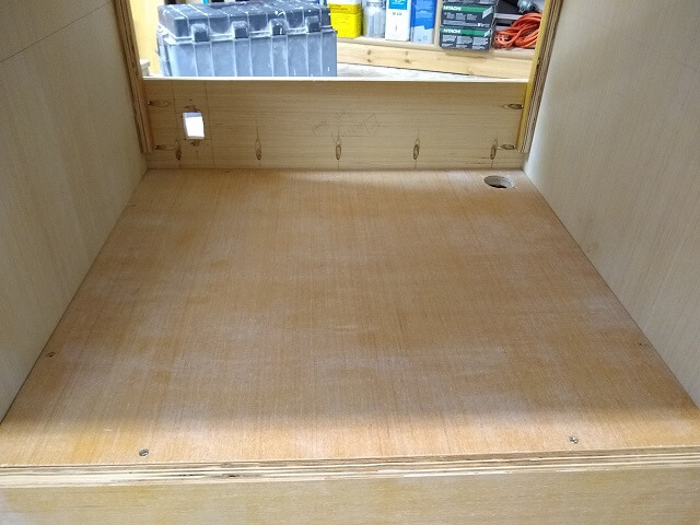
Turning the cabinet around, I mounted the PC shelf in place.
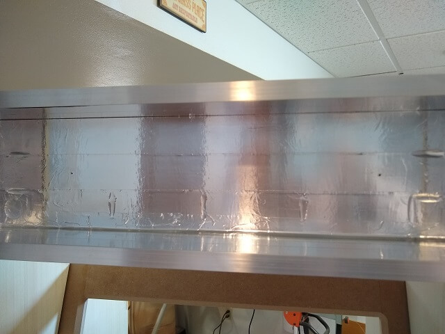
In the marquee area, I added some aluminum tape to the inside. This will hopefully help reflect the light out of the front of the cabinet instead of getting absorbed by the wood.
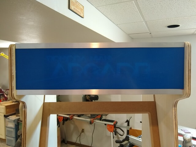
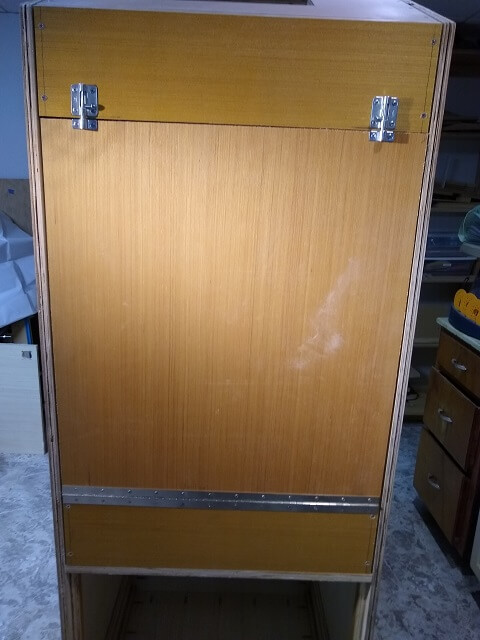
I test fit the marquee panel in place to make sure it fit. It was a bit tighter than I predicted, but it went into place. Note that I still have the protective film covering over the plexiglass, so that's why it's blue.
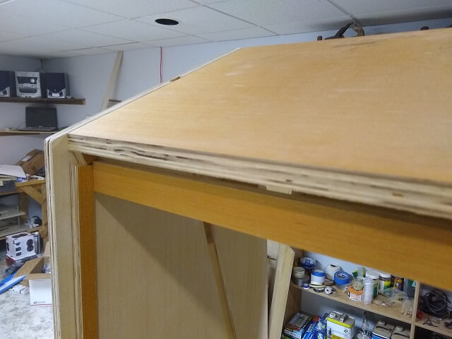
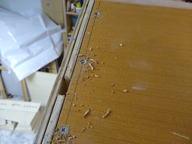
On the back, cleats were added that will hold the top panel in place. These cleats were simply glued in place. As this is an edge grain glue-up (versus end grain) no screws were needed. The cleats aren't going anywhere.
At this point I noticed a minor mistake. This turned out to be a good thing. The good thing wasn't that I had made a mistake. The good thing was that I noticed it before I went any further. When I glued the cleats in place, I happened to have the monitor bezel slid down in the slots. When I went to remove the bezel, I noticed that the cleats interfered with the pieces that had been added to the back of the bezel to position the monitor. So I wound up taking out a trim saw and removing just enough of the cleats to let the bezel slide out. I'm glad I noticed this issue now versus after I had fitted the top of the cabinet in place and/or had everything painted.
With that small "oops" corrected, I glued and screwed the speaker panel in place.
Now my attention turned to the back of the cabinet. I wanted to cut and fit all of the rear panels. These panels aren't going to be glued in place, just screwed. This way I can remove them for maintenance if necessary. To give the screws something to "bite" into, I needed to install more cleats. And in order to install more cleats, I had to cut some cleat material. I grabbed some scrap pieces of plywood hanging out next to the garbage can and sliced it into 3/4" strips.
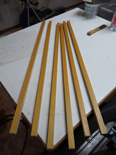
I then cut and glued the cleats into place. Again, glue would be plenty sufficient to hold the cleats without need of mechanical fasteners. The 6" (or so) portion of the back without any cleats was done on purpose. I started to think about the possible need to get a full-width panel in and out of the cabinet. If that need ever arose, it would be a lot easier to have a section without cleats to allow it to slide into place. I don't know if I will ever need it or not, but I went ahead and added the gap.
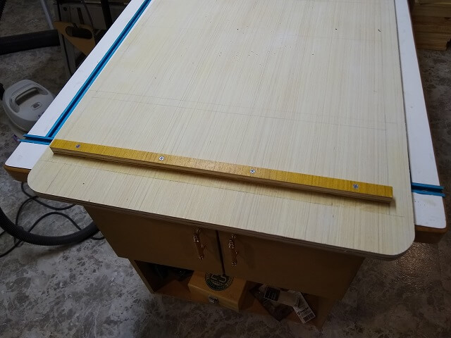
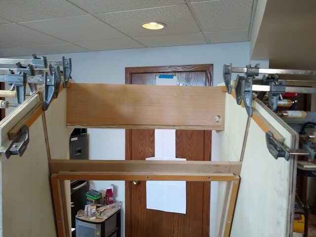
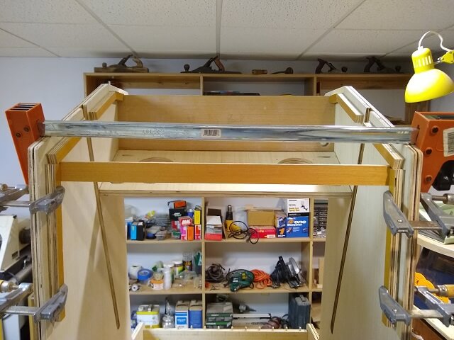
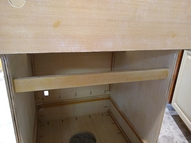
As I was moving the cabinet around, I noticed that the top rear of the cabinet was wider than 24" by about 3/16". I pulled out a straightedge and discovered that the two side panels splayed outward slightly as the side panel material wasn't perfectly flat. I could easily pull the corners into alignment with a clamp, and once the top and back pieces were attached they would hold them in place just fine. However, if I ever needed to remove all the panels in the future I would probably have to go get a clamp again. I decided it was simple enough to add a brace to the top rear that will pull the sides into the proper width even with the panels removed.
One day when I was heading down to the shop for a work session I had an idea: "What would happen if I turned the Roomba loose in the shop?" Well, there was no better way to find out than to do it. I grabbed our Roomba (I've named it "Robosuck") and placed it on the floor of the shop and turned it on. It immediately headed to the least dirty corner of the shop and spent way too much time over there. But after a couple of hours it had pretty much covered the entire floor.
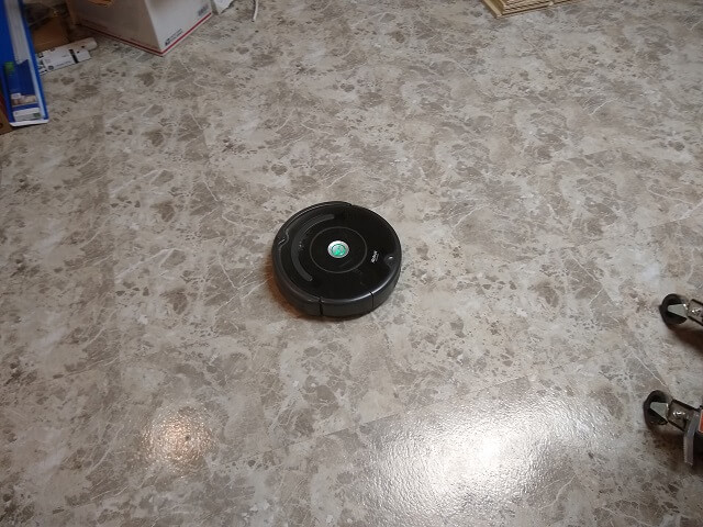
I noticed that the battery lasted about twice as long compared to when it runs on carpet. It really didn't look like it was doing anything as I could see the brushes throwing sawdust around rather than picking it up. However, once I looked in the dust bin I discovered it was packed full of fine dust. Apparently it was working, just in a different way than I had anticipated.
It also was now really dirty, so I had to give it a good cleaning before placing it back up on its base in the family room. I don't think it was super beneficial to run the Roomba compared to manually using the shop vac, but I now know it's at least an option.
Back to the cabinet construction, I now wanted to cut and fit the top panel. If viewed from the side edge, this panel would look like a parallelogram with the front and back edges being cut at a 62° angle so that they will sit flush against the other panels against which they butt up. Yes, I went through a lot of reordering to make sure that the last sentence didn't end with a preposition.
As mentioned, this panel will only be held in place with screws so it can be removed for maintenance. Specifically, this panel would have to be taken off if I want to remove the monitor bezel. I drilled countersunk holes for the screws. I also went ahead and temporarily installed the screws to make sure everything fit correctly.
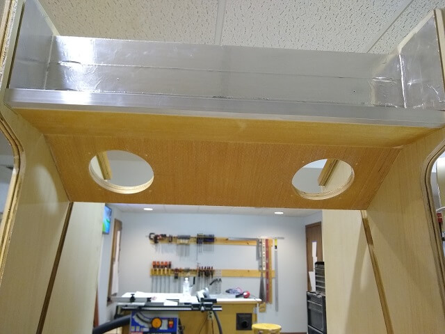
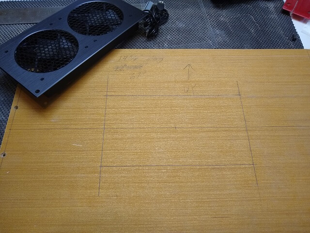
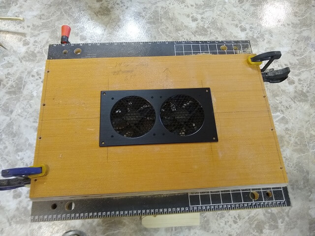
This top panel will have cooling fans installed. I pulled the panel back off the top of the cabinet and marked the lines where the fans will be located.
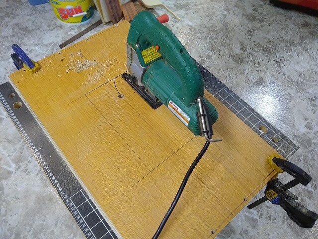
Ideally I would have liked to use my scroll saw to cut out the hole, but the scroll saw only has an 18" deep throat and I measured the panel and calculated that I would need about 21" of clearance. So no scroll saw for me. I broke out the jigsaw and used that to cut out the hole. I swapped the blade for something with a little finer teeth and that gave me a cleaner cut versus the last cut I made with the jigsaw.
With the hole cut I dropped the cooling fans into place for a test fit. It fit pretty well without any additional trimming needed, so I marked the location for the mounting screws with an awl, and then drilled the holes.
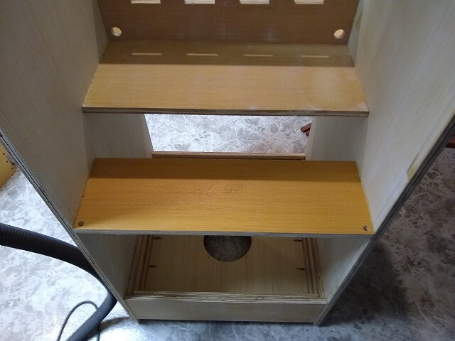
Moving downward, the next thing I wanted to tackle was the back panels. These too would be removable to allow easier maintenance. The PC shelf separates the back into an upper and a lower section, so there wouldn't be just one large piece of plywood screwed into the back.
My original idea was to make the upper portion of the back one large piece that could be unscrewed when I wanted to work on the components inside the cabinet. As I mulled over my design in my head, I started to realize that I might be needing to open it up more often than I would suspect, especially at first when I would be debugging everything. It would quickly grow old to grab a screwdriver every time I needed to tweak a component or give the computer a smack.
So, I decided to make a door that could be easily unlatched and opened up whenever I wanted to access the inside. I thought about just making the top portion of the back one large door, but that would require I would have to move the cabinet almost three feet away from the wall to get it open, and that the door wouldn't be able to swing all the way down without hitting the floor. So I wanted the door to be smaller. At the same time, I wanted it large enough for me to easily access everything inside without wedging myself through a small hole. I did a little figuring and decided a 26" tall door would be a good compromise.
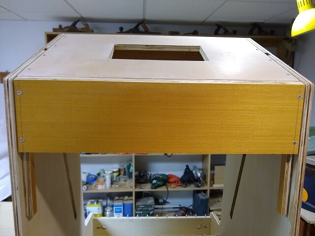
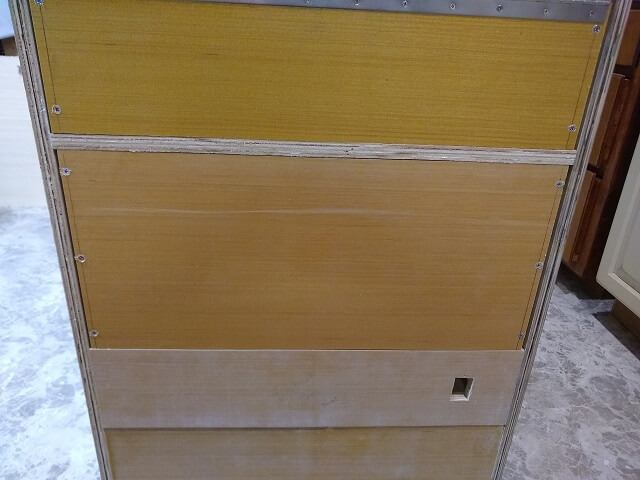
Rather than putting the door towards the top or bottom of the upper section, it would be most convenient to roughly center the door in the upper section. That would mean I would need two panels about 6" tall above and below the door. I started by cutting the top panel. The top edge needed to have the 62° angle cut in it so that it matched the angle of the slanted top. I marked the holes and drilled for the screws, then mounted the panel. I'm mounting everything up for the door so I can make sure it all fits and works properly. Then I'll have to remove all the hardware so the panels can be sanded and painted. A bit of redundant work, but I didn't trust myself to get it all correct after paint was applied.
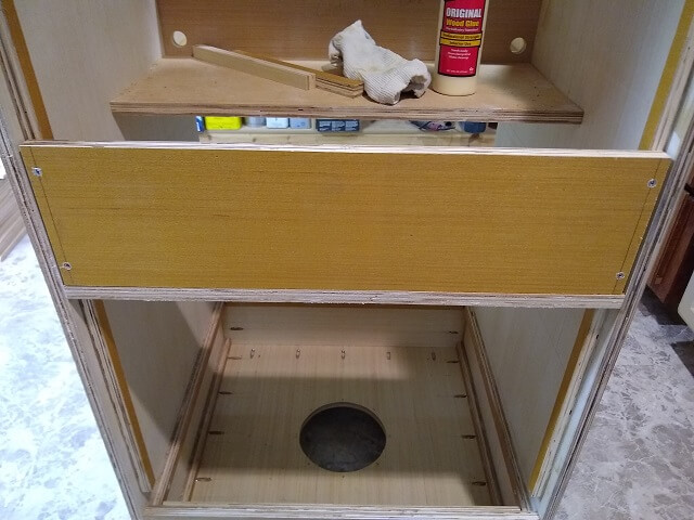
Likewise, the lower panel was cut, drilled and screwed in place. You'll notice that these panels are noticeably narrower than the cabinet, leaving a bit of a gap on the sides. This was partially intentional. I say partially, because I did want the panels a bit narrower so I could screw them in place without having to wedge them, which would make removal later much easier. The unintentional part was I had some pieces of plywood that were 23 3/4" wide, which were about 1/8" narrower than I would have liked. I decided that was "close enough", so I used them. That made the gap on either side 1/8" wide as compared to the 1/16" wide I had originally envisioned. A little more gap than I wanted, but this is the back that nobody will ever see so I was OK with it as an excuse to use these scrap pieces that otherwise may have gone to waste.
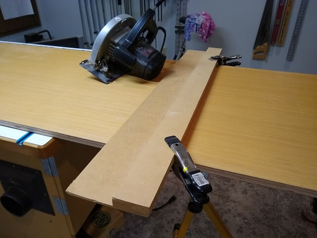
Now I needed a piece for the door. I didn't have any more of the "scrap" sitting around that was large enough, so I grabbed a big chunk of the plywood. It was larger than I wanted to try and wrestle on my table saw, so I cut the piece using my circular saw and a saw board. Unfortunately, after I cut it I realized the end of the plywood wasn't square, which made my door piece somewhat of a parallelogram. Rather than trashing it and cutting another one, I used the sawboard to trim some angled pieces off the sides. This got it close to square, but not perfect. If I were to make it perfect it would have gotten too small. Once again, I decided this was the back side that nobody ever saw, so it was close enough. And the slightly larger gaps of the other rear panels allowed me to trim this one square without making the door look obviously too small.
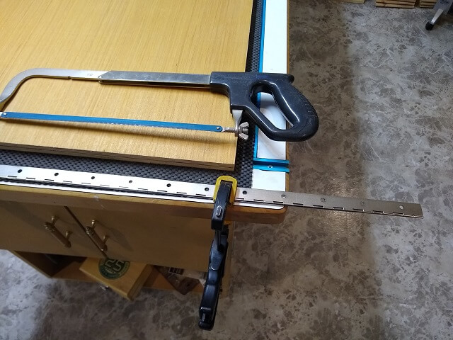
For the hinge, I purchased a piano hinge. The hinge needed to be a hair shorter than 24", but the hinge came in a 30" length. That meant I needed to trim it to size. I marked the cut line and grabbed my hacksaw. After about 10 tries to get the saw cutting, I realized that the metal used in the hinge was harder than I expected. With enough patience and stamina I could have trimmed it using the hacksaw, but I didn't have enough of either at the moment. I pulled out my Dremel tool, installed a cutting disc and sliced the hinge to length. Even with the Dremel it took about 5 minutes to cut through this hinge.
With the hinge cut, I used a metal file to remove the burrs and soften the cut end so I didn't unintentionally amputate something important while handling it. I then mounted one side of the hinge to the door panel.
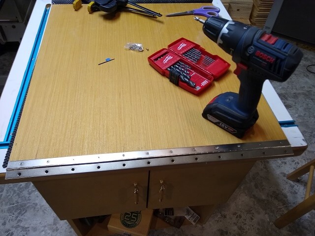
The door was then put in place and taped to keep it from conking me on the head as I drilled and screwed the other side of the hinge to the bottom piece.
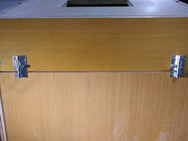
To keep the door closed I installed a barrel latch on each end of the door. One latch in the middle would probably have been enough, but as they say, "nothing succeeds like excess." I mounted the larger portion of the latches on the top panel so that gravity would help keep them in the "closed" position.
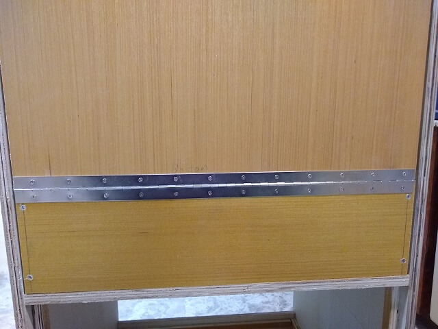
Here's the full door with all the hardware installed. It's a shame that I'm going to have to take all these screws out and then put them all back in again later.
With the latches unhooked, the door opens wide to give me good access to the inside of the cabinet, but doesn't hit the floor before opening all the way. Later on, after the project was complete I realized that it actually is long enough to hit the power socket/cord when open. That's not ideal, but not the worst problem I've ever created.
One last panel needed to be cut and mounted: the back of the storage area that sits on top of the electrical panel. Really, there shouldn't be a lot of need to remove this panel for "maintenance", but I went ahead and made it removable anyway. It probably will make it a little easier to install the drawer slides with the back accessible. This used up the last of the narrower scrap I had sitting around, so again the gap is a bit large. At least it matches the rest of the back.
Moving around to the front side, a piece was cut that will be used to mount the keyboard door. Before this piece was glued in place, holes were drilled for the piano hinge that will mount the door. This needed to be done first, as once the piece was glued in place there wouldn't be room above it to fit a drill to make the pilot holes. With the hinge holes drilled, this piece was then attached to the cabinet with glue and pocket screws.
One thing I neglected to do was test fit the keyboard door. I got lazy and didn't want to fasten all those piano hinge screws into place. Later on, after the cabinet was painted and I was putting everything together, I discovered that my keyboard door was a little too big. It fit in the opening just fine when closed, but when swinging open the diagonal height of the door prevented it from clearing the top of the opening. I wound up having to trim a little bit off that piece and then repaint it. Had I tested it now I would have saved myself the hassle of repainting.
I could now install the top panel of the subwoofer box. Before I put it in place I went around all of the seams inside the box and sealed them with silicone caulk. Generally, the more airtight a subwoofer chamber is, the better it sounds. I then placed the panel inside the cabinet and screwed it in place. I used screws instead of glue thinking that this panel could be removable if I ever needed to take it out to do maintenance. However, after the other pieces of the cabinet were coming together I realized that it would be impossible to remove this panel without major surgery. So this panel is now permanent. Had I realized this sooner I could have installed it without making the screw heads so obvious. Oh well, they will be inside the cabinet under a drawer and rarely seen so it's probably not a big deal.
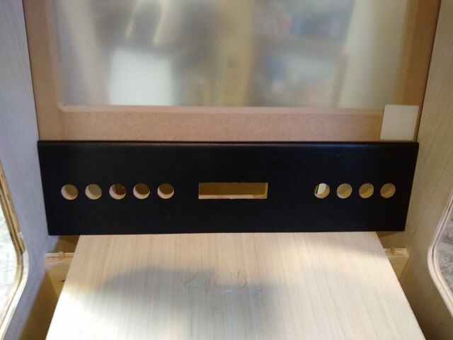
I covered building the upper control panel on the previous page. Now it was time to add it to the cabinet. I carefully put it in the correct place in the cabinet and used the pocket screws to affix it to the cabinet sides. Because the cabinet is still unfinished, and this control panel has vinyl covering glued to it, I will have to carefully tape off the panel when painting the cabinet later on.
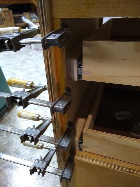
I cover making and installing the drawers on the next page. After the drawers were done I could start building the lower cabinet door and face frame. If not sized correctly, the face frame could hinder the operation of the drawers by not allowing clearance between the door and the drawers. Because of this, I decided to hold off on making the frame and door until I could see exactly where the drawer slides would be located.
Once I got the drawers in place I did some measuring and determined the size of the face frame. The hinge side was pretty straightforward; just a piece roughly 7/8" wide glued in place.
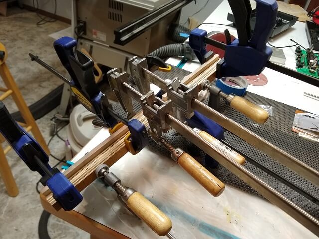
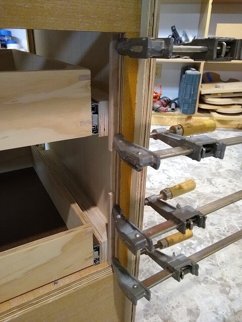
The latch side was a little more complicated. It needed a deeper section to hold the latch, along with stops to keep the door from swinging inward too far. I glued the various pieces together on the workbench rather than trying to do it in place.
With the latch side face frame assembly created, it was glued in place on the other side of the cabinet front.
With the face frame in place I measured the opening and cut a piece of plywood for the door. The door was cut 1/8" smaller than the opening to allow for 1/16" of clearance all the way around. I figured this would be a little tight, but I could always trim the door smaller as needed when test fitting.
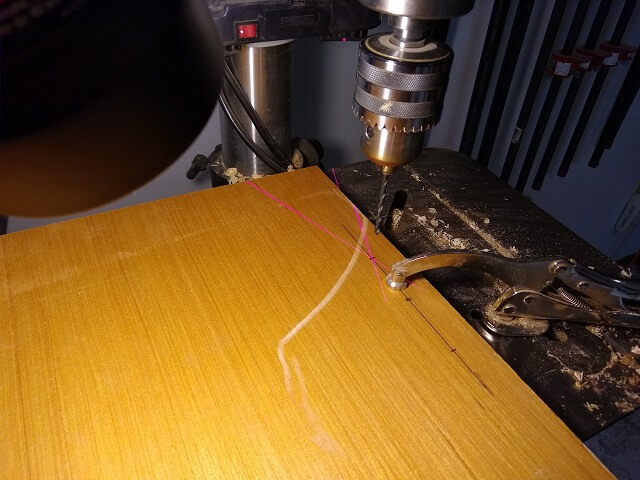
Holes for the cabinet handle were drilled. I did this on the drill press because I wanted them to be perpendicular so I didn't have any binding when trying to install the handle.
All of the door hardware was installed, which included the piano hinge, the latch and the handle. These would all have to come off again prior to painting the cabinet, but I wanted to make sure everything fit properly. It's a lot easier to correct any issues now before paint is applied.
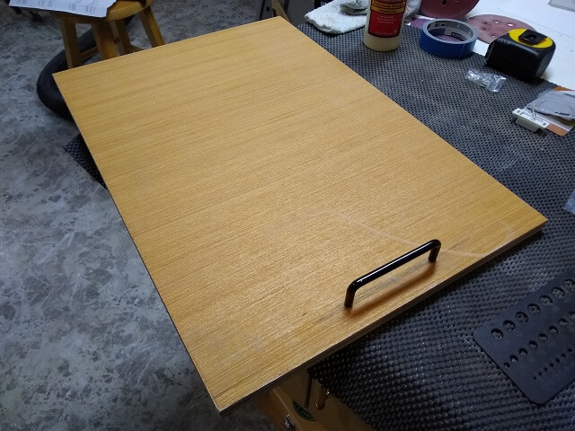
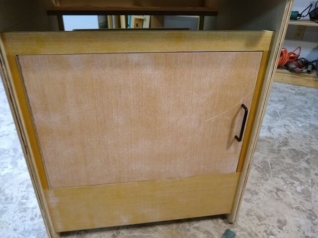
I mounted the door on the cabinet to see how it fit.
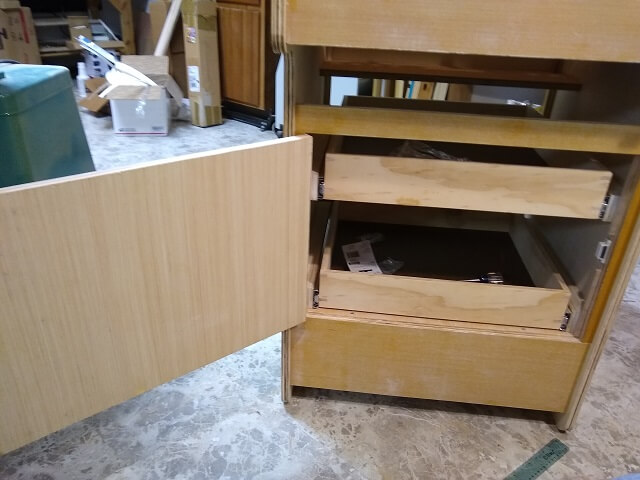
As it turned out, it was very close but one side of the door rubbed just a touch. I trimmed another 1/16" off this edge to make it close without any binding. Unfortunately to trim the door I had to remove all of the hardware and then reinstall it again which was kind of tedious. However, it was a necessary step and in the end was worth the hassle to ensure the door fit correctly.
We're almost done with the cabinet shell construction. Lets talk about how I built the drawers.
Return To The Main Wood Gallery
This page last updated on 09/21/2023