


For the first 20 or so guitars I made, I radiused the fretboards using a sanding block with a concave radius that was the mirror image of the convex radius needed on the face of the fretboard. It worked, but it had some limitations.
- It took a long time. Usually at least an hour, sometimes more with dense woods such as ebony.
- Related to above, my hands would become raw after an hour or more of pushing the sanding block back and forth.
- After an hour of breathing fine ebony dust, I would blow black boogers out of my nose for quite a while.
- If a person wasn't careful, it was easy to sand some areas of the fretboard too much, causing an uneven fretboard that would later be noticeable when leveling the frets.
- The width of the fretboard I could radius was limited to the width of my sanding block, which was about 3".
For years I had thought about buying or building some sort of jig to allow me to use a power tool to do this monotonous job faster and with less effort. I would toy with the idea and do some half-hearted research, then forget about it until the next time my hands were hurting while sanding a radius. Most of the solutions I found were either horribly expensive (i.e Grizzly's fretboard radius sander), not flexible (can only do one radius size unless you want to build multiple jigs), too large requiring lots of storage space or all-around rinky-dink looking.
When the Tundra Boy was building his Six String Bass, it had a 3.5" wide fretboard a the lowest point. He needed a way to put a radius on this huge fretboard, and my sanding block just wasn't going to cut it (pun somewhat intended.) So with this pending need, I started a more serious search into finding a solution to my fretboard radiusing woes.
I came across this jig at Blackwater River Guitars that checked a lot of the boxes for which I was looking. It used a mini-router, which aren't terribly expensive. It could do nearly any radius I would want, and could be built to handle any size fretboard. It didn't require tons of storage space. Finally, the design was simple enough that it looked like it would be solid to use and accurate.
Blackwater's site was pretty good at showing lots of pictures of the completed jig, but didn't really show how it was built. I had to reverse engineer things from looking at their photos. While I was building my version, I figured I would document the process in order to give others a better idea of how everything would come together.
The jig is made of three separate parts. The first, and most complex part is the sled on which the router is mounted. The second is the radius sled which will sit between the router sled and the jig base. Multiple radius sleds can be made, one for each size radius you want to be able to cut. Finally, the most simple part is the jig bottom to which the fretboard will be affixed.
For supplies, I mostly used 3/4" MDF. I also had a bit of 3/4" and 1/2" scrap plywood that I used in spots where I didn't feel MDF would have the strength I wanted. Also, I used a small piece of scrap 1/4" hardboard that was used as the base of the router sled. I also used some wood screws of various sizes, and a bit of Titebond glue.
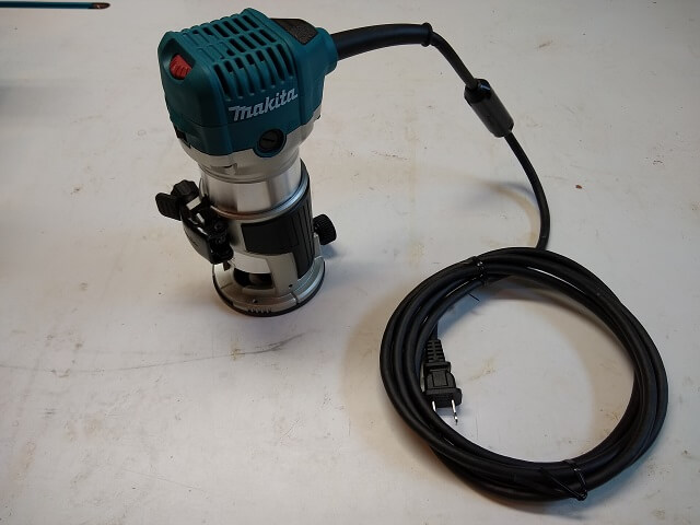
First things first, I needed a router. I had four routers sitting in my router storage area, plus a Dremel-style tool. The routers were big, which could work but would mean the jig would be that much larger. The Dremel was small, but didn't have a good way to mount vertically which would mean I'd have to do something rinky-dink. I decided this would be a good excuse to buy a new tool, so I went out and purchased a mini-router. I looked at four or five options available at my local tool store, and finally settled on a Makita. It's a respected brand, had the features I wanted and was the cheapest option (outside of Harbor Freight.) I wasn't super thrilled about the way the height adjustment works (difficult to make fine adjustments,) but I figured it was good enough to live with it.
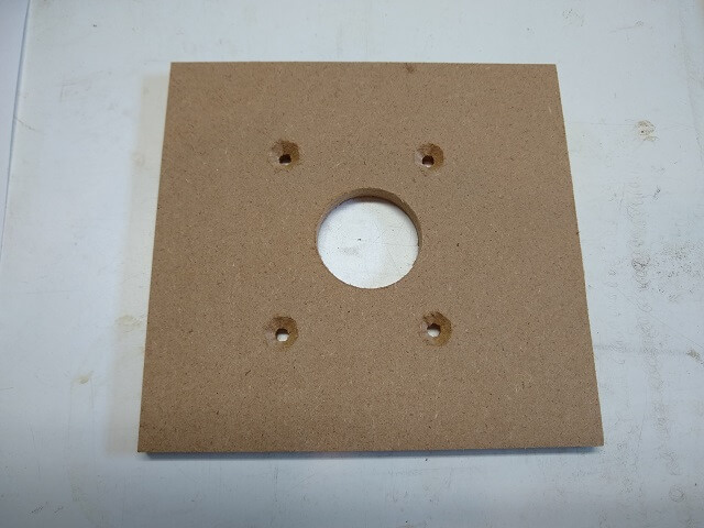
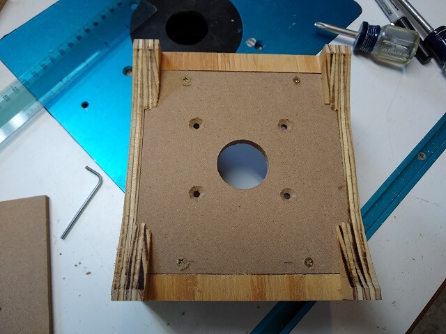
I started by building the most complex piece first: the router sled. From my scrap pile, I grabbed a piece of 1/4 thick hardboard and cut it into the size for my base. I was thinking a 4" square area for the router to sit in would be about the right amount of space. I added 3/4" in one direction and 1" in the other to give room for it to overlap into the adjoining pieces. I drilled a hole in the middle for the router bit, and then drilled and countersunk holes for the router mounting. Note that the router mounting holes aren't equidistant to the center hole. This wasn't a mistake, the Makita router's mounting holes are this way.
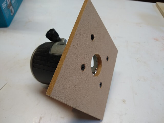
I unscrewed the factory base from the router, and screwed it into this hardboard piece I just made. One of the things I liked about the Makita was the quick release to remove the router motor from the base to make changing bits easier. My Dewalt router does this and it's much more convenient than my old Skil and Craftsman routers that don't allow this.
Next, I cut a couple of 1" wide strips of 3/4" plywood. These will be the rails to which the hardboard base is affixed. I cut a 1/2" wide rabbet a 1/4" deep on the bottom of the plywood strips to let the hardboard sit flush with the bottom of the rails. I wanted the hardboard on the bottom to give me the most depth of cut with the router bit. I used plywood because it holds screws better than MDF and eventually the hardboard would get screwed to these rails from the bottom. Also note that I had to notch one of the rails to allow clearance for an adjustment knob on the Makita router. If you build one of these yourself with a different brand/model router, you may or may not need this notch.
Two pieces of 3/4" plywood were cut to be the sides of the router sled. The width was sized to be the same length as the hardboard base plus the rails. The height was kind of arbitrary. I just made sure that once the router was sitting in the sled that the side height didn't interfere with the quick release lever. A dado was cut on each of the side pieces in order to hold the two rail pieces. Also, it is very important that the bottom of the dado is 1/2" up from the bottom of the side pieces.
Here's why the dados need to be 1/2" from the bottom of the sides: the middle section of the bottom gets cut away to form the portions of the router sled that will ride on the radius sled. Note that only the four ends of the router sled will actually touch the radius sled. This is by design, as by cutting away the middle portion (as opposed to making a smooth radius) it will allow the router sled to be used on almost any size radius. I calculated it out and my router sled will work down to a 7" radius. I never use anything tighter than 10" so this is plenty for my needs.
Holes and countersinks were drilled in the sides of the router sled, and the side pieces were screwed to the rails. Glue would have been more secure, but I wanted the ability to disassemble the router sled in the future in order to replace the hardboard base. My reasoning was if I happened to burn out the router (not expected, but a possibility) I wanted the ability to change brands/models without having to rebuild the entire router sled. By using screws I could just build a new hardboard bottom piece to match the new router if necessary.
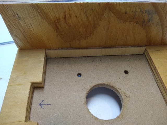
Likewise, I drilled and countersank holes for the screws that would hold the hardboard base to the plywood rails.
This probably wasn't necessary, but the gaps in the dados were bugging me. The dados were (almost) 3/4" wide to hold the plywood rails, but the hardboard was only 1/4" tall. This left about a 1/2" space in the middle of each side. I cut a couple of pieces of plywood scrap to fit these gaps and glued them in place.
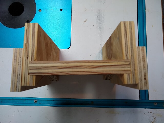
Hypothetically, the router sled could now be used as-is. However, because the radius sled is introducing side pressure to the router sled, it would have the potential of sliding off the rails and spoiling my work, or worse yet spoiling my fingers. Two pieces of 1/2" plywood were cut and screwed to the sides of the router sled, hanging 1/4" lower than the sides of the jig. These pieces will act as guides to keep the router sled from falling off as the bit spins at 30,000 RPM.
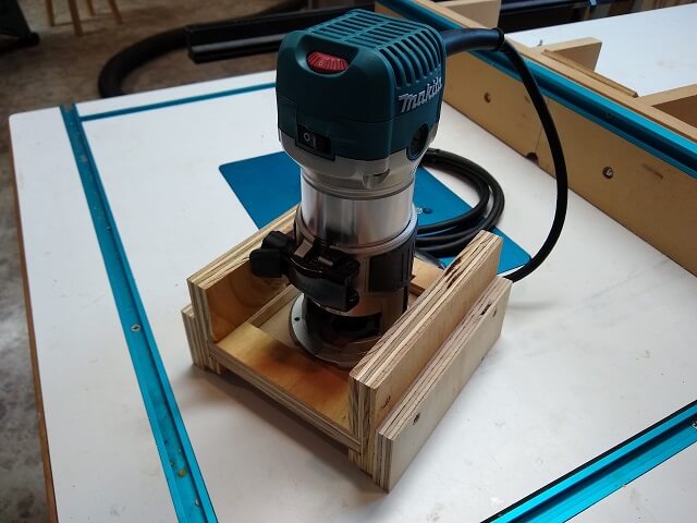
Here is the completed router sled with the router attached. This third of the whole jig took about four hours to build, which was a bit longer than I expected it to take. Thankfully this was the most complicated piece of the jig, so the majority of the work was done.
Now my attention turned to building the radius sleds. I need to to build a sled for every radius I want to use. In my case, I most frequently use 12", followed by 10". The Tundra Boy's bass was going to use a 16" radius. I figured while I was at it I might as well make a 14", even though I don't know if I will use it or not. In the future I can always make more radius sleds if there are additional radiuses I want to use, but for now these four should cover me.
Making an accurate radius cut can be difficult. A couple years ago I built a circle cutting jig for my band saw when I built the Tundra Boy's snare drum, so I was already set up to cut curves. I just had to add four new position holes to the circle cutting jig for the four radiuses I needed. Then it was simply a matter of cutting the various pieces. I needed two pieces for each radius sled I wanted to make.
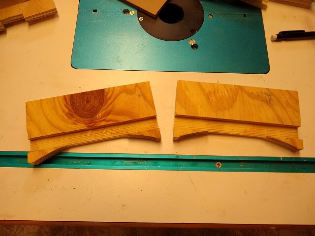
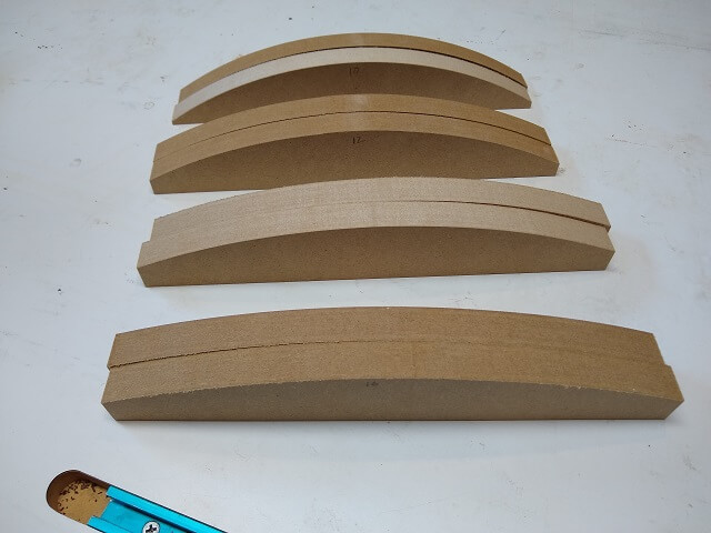
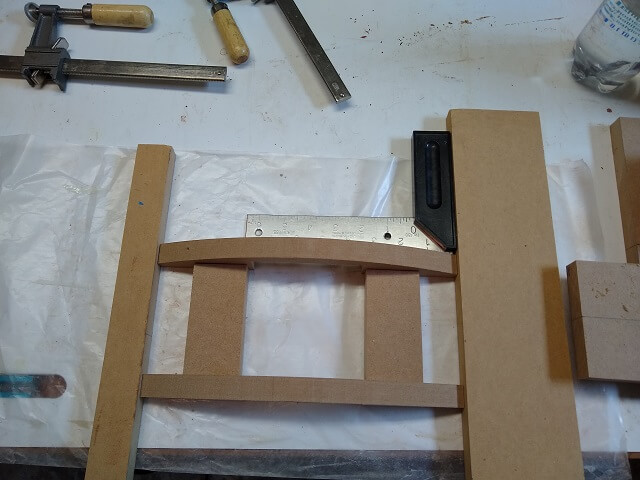
Here are the four pairs of radius rails after they were cut. They are 11" long, and 1.75" high at their peak. Lined up together it is easy to see the difference in curve between a 10" and a 16" radius.
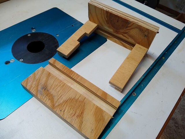
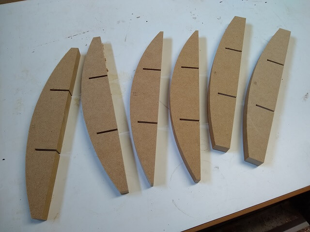
Each rail needs to have a notch cut out of the middle that will allow it to slide over the center rib of the bottom of the jig. These notches should be centered on the rail, and sized to the exact width of the center rib, plus a hair more (like 1/32"-1/16"). Too tight and the radius sled won't slide on the jig smoothly. Too loose and it will wobble around and not be accurate. I used the table saw and made a cut 1.25" deep on each side. The measurement to the outside edges of these two cuts are to the above specifications.
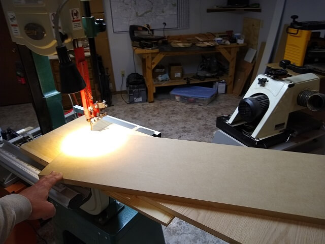
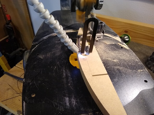
To remove the center portion of the notch, I used my scroll saw. With a coarse bit it only took about 10 minutes or less to cut all eight rails.
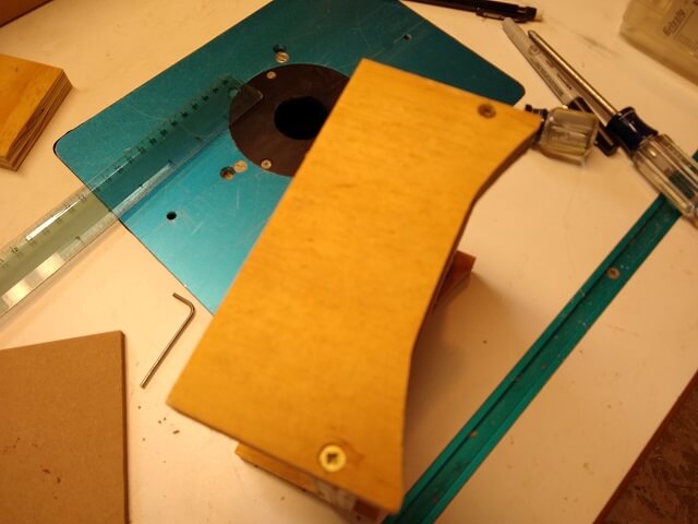
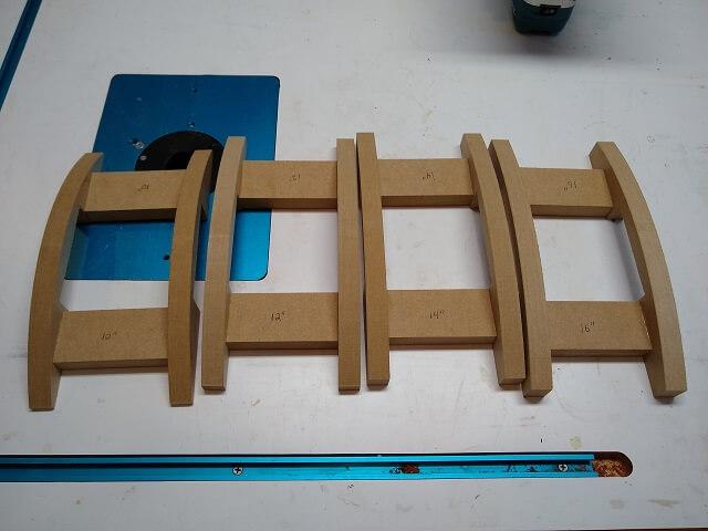
Here are all of the radius sled rails after they had the notches completely cut out.
Next, I cut 8 pieces of MDF that will be the spacers to hold the rails together. These pieces were sized to give the radius sled rails the same width as the router jig sled rails, minus about 1/32" to allow it to move. MDF doesn't hold screws very well, so I decided to use glue. However, MDF also can be problematic when gluing edges because the fibers soak up so much glue that it can starve the joint. The solution to this was that I rubbed a thin layer of glue on each end of the spacers, then allowed it to dry for about an hour. That would allow the edges to soak in the glue, and then when I would actually glue the pieces together the glue would form a strong bond.
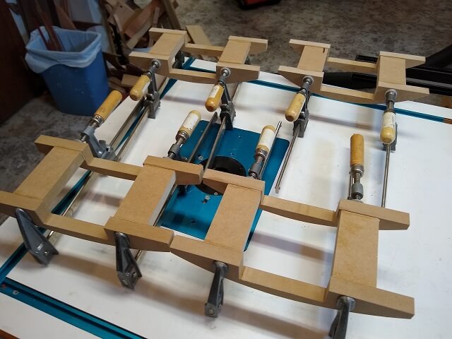
One thing I quickly noticed when starting to glue the radius sled pieces together was that it was easy to get things out of square. I used a couple of boards with straight edges and my try-square to make sure things stayed true when I clamped them up. The position of the spacers between the rails wasn't critical, so I just eyeballed them. The only thing I had to worry about was to make sure they didn't overlap the center notch, and that they weren't lower than the bottom of the rails. I positioned mine about 1/4" in from the notch, and about 1/32" up from the bottom of the rails.
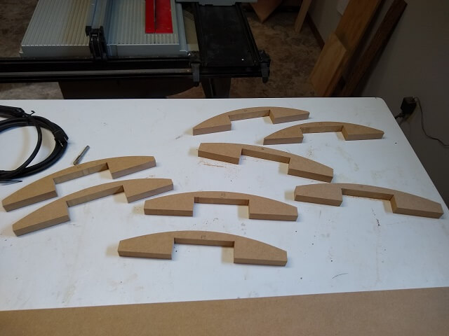
Here are all four radius sleds sitting in the clamps waiting for the glue to dry.
Now the third and final part of the jig could be made: the base. It consists of just two pieces, both of which I cut to 32" long. This length will allow me to radius fretboards up to a 35" scale length, which is as large as I can ever see myself using. The bottom piece is 11" wide to match the length of the radius sled rails. The center rib piece was 4" wide (this width also dictates the width of a fretboard you can radius, so adjust accordingly.
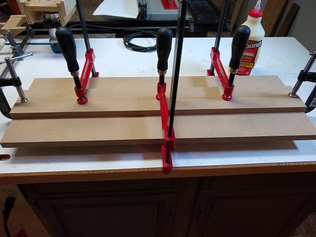
The center rib had a line scribed down the middle to help in positioning fretboards accurately. Then the center rib was glued to the exact center of the bottom piece. I took care to only spread glue in the middle of the center rib (keeping it about 5/8" away from the edges) so no squeeze-out would interfere with the radius sled's ability to slide. Then I clamped it all up and waited for it to dry.
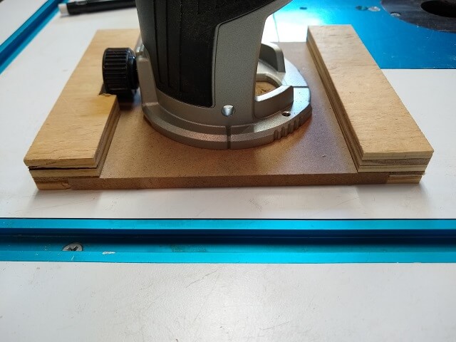
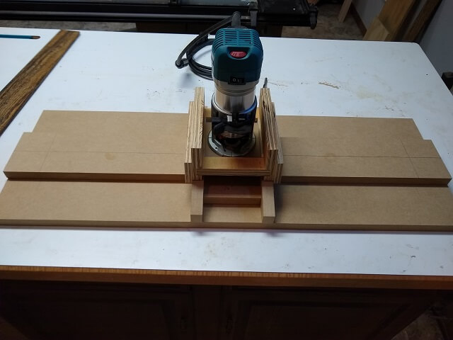
So here is what all the pieces put together look like. From the orientation of this picture, the router sled allows the router to slide on the Y axis over the rails. The radius sled can then slide on the X axis down the length of the fretboard. A 1/2 straight bit in the router is what I use.
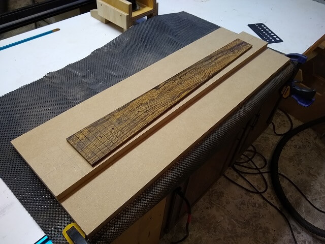
Time to take the jig on its inaugural run! The Tundra Boy used double-sided tape to affix his fretboard to the center rail, taking care to line up the center line on his fretboard with the center line on the jig.
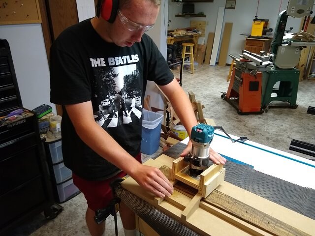
Starting at the edge of the widest portion of the fretboard, he lowered the bit until it would just shave a little bit of wood off. Then he turned on the router and pushed the two sleds down the fretboard until the bit no longer made contact (due to the taper of the fretboard.) He then moved the router sled a little bit in on the radius rails, and made another pass down the fretboard. Once the bit had raised high enough on the radius that it was no longer making contact, he repeated the process on the opposite side of the fretboard.
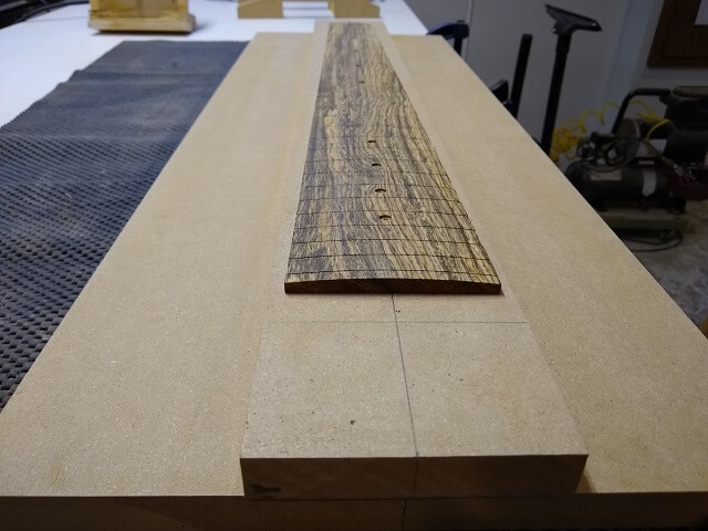
The above routine was done several times, lowering the bit just slightly between each itteration. Once the bit was lowered so that it just grazed the center of the board, he was done.
The results were good. The radius was very consistent. It was surprisingly smooth for using a router, although it will need some finish sanding. It also took about 1/2 an hour and didn't generate any sweat. Now that he's done it once and gotten used to how it all works, the Tundra Boy figured it he could do more fretboards in closer to 15 minutes. That's a significant time savings over the old sand and complain method.
So there you go. Hopefully my description of how I built my jig will help if you decide to build one of your own.
Return To The Main Guitar Gallery
This page last updated on 07/29/2020