


With the basic body shape cut out and sanded, it was time to start shaping the body and cutting out the cavities for the controls, pickups and neck. Because I am planning on binding the front edge of the body where the maple cap attaches to the mahogany back, I will leave the top flat and the edges square. A flat back with square edges, however, would probably not be very comfortable to play and also would make the body look like it was carelessly cut out of a big chunk of wood. Ironically, guitars are cut out of a big chunk of wood (hopefully not carelessly) but asthetically we find the softer, more contoured shapes to be more pleasing to the eye. There are many options for contouring the back edges of guitars. I decided to use a method similar to the one used on a Fender Stratocaster, where the edges are profiled with a 1/2" round-over and there is a "comfort contour" (aka beer belly profile) on the back side.
To begin, I chucked up a 1/2" round-over bit in the router table and rounded over the edges of the back side. Because I would be switching grain directions as I went around the body, I cut the round-over in 3 different passes. I had the router power to take the full depth in one pass, but doing so would have risked some nasty tear-out. It was a little more work to raise the bit slowly and make multiple cuts, but the additional piece of mind it bought me was well worth it.
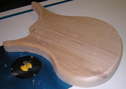
Once again, I ran into a snag for which I hadn't accounted. I rounded over the entire back edge of the body: including where the neck will attach. This will leave me with less room in which to shape the neck profile later on. Not the ideal situation and I should have made better plans to account for this, but I think it is a salvageable mistake. We'll see when we get to that part of the guitar!
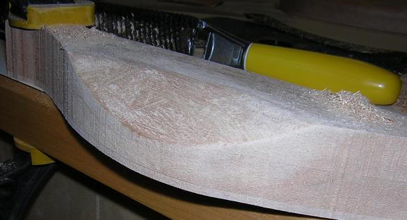
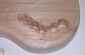
Now it was time to make the beer belly recess. This was to be a curved cutout on the back side of the body that will allow the guitar to sit a little more flush against the bodies of most of us who live in North America. Because of the curve, it wouldn't have been an easy thing to use a power tool to do the carving. I suppose a Dremel might have worked, but that seemed tedious. I've heard of people cutting these recesses on a band saw, but that didn't sound like something I was ready to try. So, I decided to rely on good old hand tools. I got a surform with two blades (one flat and one curved) to rough carve the recess. Seeing as I had never done any carving before, I thought it would be good to give it a practice run on some scrap. I pulled out a chunk of the body off-cut, marked a contour and went to town. To my surprise, it was much easier than I had anticipated. I just had to remember to go slow and try and make the recess nice and even.
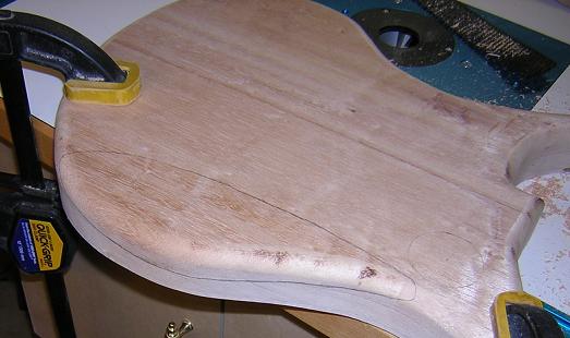
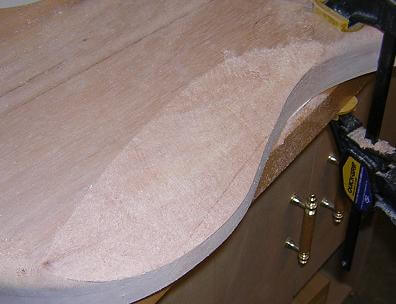
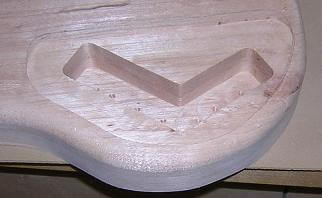
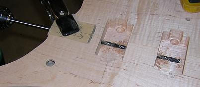
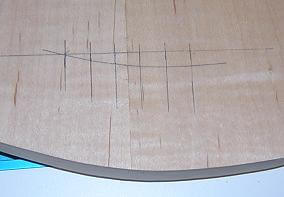
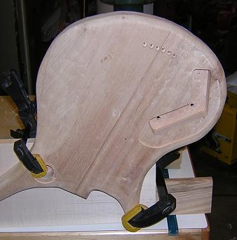
Satisified that my practice had made me an "expert," I clamped my body to the edge of my workbench and carefully drew in the lines of the countour with a pencil. In the picture below, you can also see where I've marked the position of the 3-way switch cavity. I wanted to make sure to form the contour in a way that wouldn't interfere with the switch cavity. After a little erasing and refining, I had a contour shape in which I was satisfied.
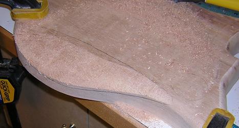
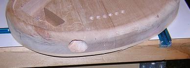
There's not a lot of description to cutting the contour. I used the round surform blade on the edges of the contour to help give it the gradual taper, then switched to a flat blade to hog out the majority of the wood. I took a few rest breaks (this is labor) and checked my progress against the layout lines. When I finally had the rough shape done, I switched to sandpaper to smooth out the gouges. This actually took longer than cutting the contour, as the surform leaves a very rough surface. When I would get the contour smooth, I'd wipe it down with naptha and that would reveal additional scratches I had missed. Total time was about 15 minutes carving and about 25 minutes sanding. But the end result turned out much better than I had anticipated for my first carving effort. After seeing the contour, my wife remarked, "wow, it's actually starting to look like a guitar!"
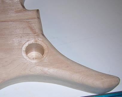
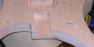
Now it was time to work on the control cavities. Because I am using a 3-way switch in the Les-Paul location, I needed to have two cavities. I started with the switch location on the upper horn, as this was the easier of the two. First, I used a 1 3/4" forstner bit on the drill press and drilled an 1/8" deep hole for the cavity plate. Then I switched to a 1 1/4" bit and drilled the cavity, leaving 1/4" of wood on the guitar face side.
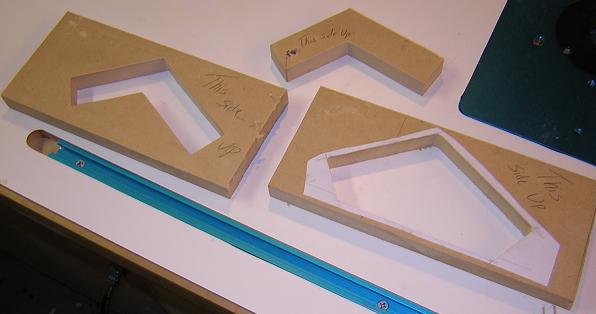
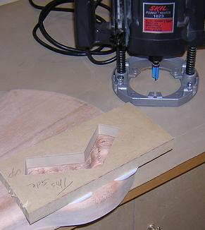
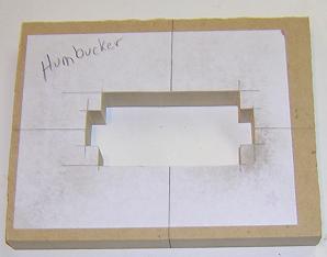
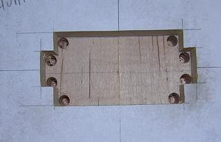
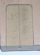
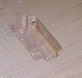
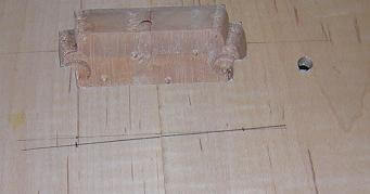
With the switch cavity complete, I moved on to the control cavities. Seeing as the cavity wasn't going to be round I couldn't use the simple forstner bit method as I had with the switch cavity (drat.) For this cavity, I was going to have to make some templates an use the router. I sketched out two different templates: the first would be used for the deeper recess to hold the volume, tone and input controls, and the second would be used to rout out the 1/8" recess for the cover plate. I glued these outlines to pieces of MDF and cut them out on the scroll saw. In the picture below, you can see the templates. After I took this picture, the template on the right (for the control plate recess) was replaced with one with a more round shape, as I didn't care for the first angular one I came up with.
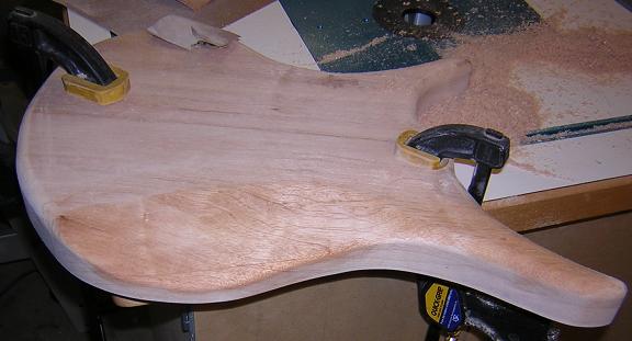
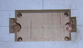
I laid the two jigs in place on the guitar body and used a pencil to rough-in their locations. As you can see in the photo below, I moved it around a couple of times before I was satisfied with their final positions. Once I had the positions marked, I used a forstner bit in the drill press to remove the majority of the waste in the control cavity, as this would make things easier on the router and the router bit.
With the majority of the waste removed, I used double-sided tape to attach the jig and then used a pattern cutter bit to remove the rest of the wood from the cavity. As a side note, I've found that as long as I clean the sawdust off the jig and the workpiece, the double-sided tape is plenty strong to keep the jigs in place. In fact, if I use too much of it it's a little hard to pry the jig away. The final depth of the control cavity was to be 1 1/8" deep (and maybe a hair deeper.) Because my pattern cutting bit in the plunge router only let me cut 7/8" below the 3/4" template, I had to rout the cavity in two steps. First, I routed with the template as deep as I could, then I removed the template and ran the bearing of the pattern bit on the top edge of the cavity in order to achieve the final depth.
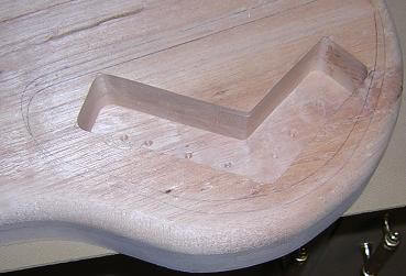
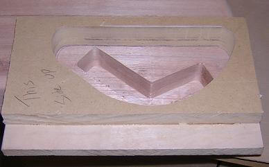
Routing the cover plate cavity was done in a similar manner, but with a different jig and without using the forstner bit to hog out the waste. The depth only had to be 1/8", which was plenty easy for just the router. Because the depth of the cut was so shallow, and my pattern cutting bit blade was 1" long below the bearing, I had to make the jig extra tall. I glued a piece of 1/2" plywood to the 3/4" MDF prior to cutting it out on the scroll saw. Another thing that I discovered while routing was that the edges of my jig were very narrow, which made balancing the router a trick. I had to be very careful when routing the edges in order to make sure I didn't tilt the router and spoil the workpiece. For future guitars, I'm going to re-make this jig to provide better router support on the edges. Another option would be to build an extended base for the router, but redoing the jig would be easier.
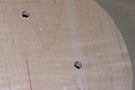
With the control cavity finished, I drilled two holes for the volume and tone knobs.
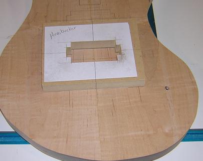
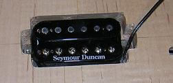
This completed the shaping of the rear of the body (at least until I glue the neck in place.) Now I turned my attention to the front of the body. This guitar will have two humbucking pickups, so I created a jig that will allow me to rout them:
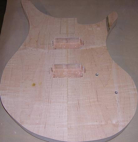
With a pencil, I figured out where on the body I wanted the pickups located. I used the center line of the maple top as my reference point to align the pickups horizontally, then decided the vertical alignment based off the bridge and the bottom of the fingerboard. With the positions marked, I attached the template jig to the front in the spot marked for the bridge pickup.
Because the humbucker jig did not allow for much clearance room around the outside of the pickup, and because my pattern cutting bit is a 1/2" I needed to make sure my corners had the necessary clearance. To do this, I started by using a 1/4" brad point bit and drilled out all of the corners. I drilled to the same depth as the final pickup cavity (7/8").
On either side of the humbucker, there needs to be additional clearance allowed for the mounting screw. To create this clearance, I used a 1/2" forstner bit and drilled to a slightly deeper clearance (1 1/8") on either side of the pickup cavity.
Once again, to lessen the tax on the router I removed a majority of the waste area with the drill press and a forstner bit.
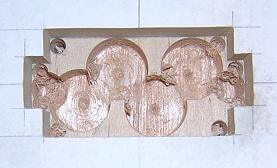
Then I removed the remainder of the waste with the router and removed the jig.
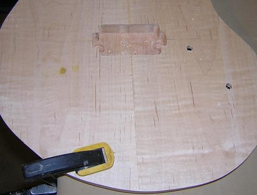
Just to make sure everything fit OK, I tested the pickup in the cavity. Better to tweak things now than after the finish has been applied!
Then I repeated the process for the neck pickup hole. As an interesting side note, the yellow stain on the left side of the body was the evidence of the former life of a boxelder bug that was on my workbench when I clamped the body down. I really hope it sands out later, otherwise I'll have an interesting coloration. Thankfully, it exists right where I'll place my arm, so if it won't come out it should at least be hidden!
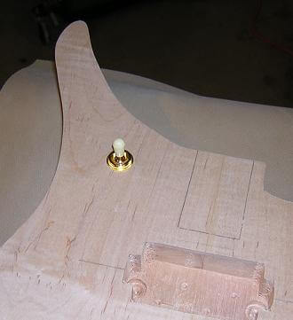
At this point I completed the pickup selector switch cavity by drilling a hole through to the front. The only reason I waited to do this step after drilling out the access hole was because I didn't have the switch ordered yet, and I wanted to make sure I drilled the correct sized hole. In the picture below you can see the test mounting of the switch. The 1 1/4" diameter cavity is just barely large enough to accomodate the switch. I may have to tweak it just slightly with the dremel once the wires are soldered into place.
Next up was to rout the neck pocket. Once again I created a simple jig to allow me to use the pattern cutting bit. I taped the jig in place, making sure that I had it centered properly with the center line in the maple top.
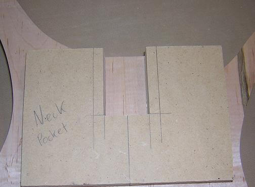
Again, I used a 1 3/8" forstner bit to hog out a majority of the waste. Setting the pattern cutting bit for a 7/8" deep cut, I routed the neck pocket to final depth and size.
With the neck pocket cut in the body, I was going to have to create a tenon on the end of the neck that fit precisely in the pocket. I didn't want a sloppy join here, as this is the most important join on a guitar, both structurally and tone-wise. Frankly, I don't trust my woodworking skills enough to think that I could get it dead-on just by cutting the neck end. So, once again I turned to a jig. I figured that I could tweak the jig until I'm happy with the join, and if I messed it up I could toss the jig and start over. Not so easy to start over with a new neck. Once I had a jig that fit well, I could tape it to the end of the neck blank and use the pattern bit to rout a perfect tenon. In addition, I needed to drill a hole between the two pickup cavities to allow the wiring to be run between them. Usually this is done via a hole drilled through the end of the neck pocket, then through the two cavities. The hole in the end of the neck pocket is traditionally left open.
Editor's Note: (Hey, isn't this whole site "editor's notes?" Anyway...) In the description that follows I describe a modified neck joint that utilizes a dowel. This is another example of what happens when you write about each step in sequence, but work on mulitple steps concurrently. I wrote most of this page prior to my first neck going south. When I had to create new neck pocket and tenon jigs, I scrapped the idea of trying to put a dowel at the end of the tenon, mainly because I knew the pocket wasn't square and that the chance of me getting that hole properly lined up were close to nil. Maybe I'll try it on a future guitar, assuming I live through this one. But for now, just make a mental note that the dowel idea was left in conception stage.
I started to give this wiring hole some thought. "Why can't I center the hole in the end of the neck pocket, then drill a corresponding hole in the end of the neck, then add a dowel to this joint?" So that's what I'm planning to do. I drilled a 1/4" hole through the center of the tenon jig. I'm hoping that this dowel will help increase the strength of the neck pocket and also prevent glue squeeze out from entering the neck pickup cavity.
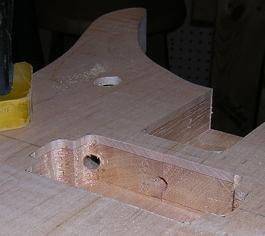
Here's a shot of the drilling of the dowel hole and the wiring hole. I used an extra long 1/4" drill bit. Actually in the photo below, you see an early version of the neck tenon jig. I hadn't yet rounded off the corners; sometimes I tend to get ahead of myself.
Along with the wiring hole between the pickup cavities, I also needed a wiring hole between the neck pickup and the pickup selector cavity, and from the bridge pickup to the control cavity. I used the same extra-long drill bit and drilled the holes at a steep angle. I was extra careful not to mar the top of the guitar with the drill bit or chuck, and to drill at a steep enough angle that I would not accidentally protrude through the back of the guitar.
Now it was time to drill the holes for the bridge and where the strings will go through the body. In lieu of a traditional tailpiece, I decided to run the strings through the body. This was done mainly for asthetic reasons, though some would argue that doing so increases the sustain of the guitar. I mainly wanted something a little different, and it was cheaper than buying a tailpiece. First I had to mark where the holes will be drilled. I wanted them to line up exactly with the bridge, so I took some time measuring and marking. Also, rather than drilling the holes perpendicular to the center line, I followed the contour of the bottom of the guitar.
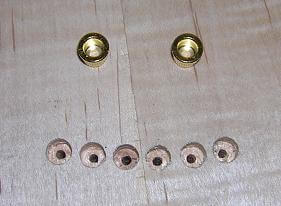
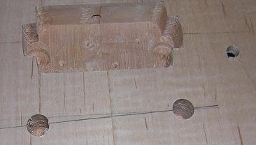
With the locations marked, I carefully drilled through the body using the drill press to keep the holes straight. Both sides of these holes will have a gold "ferrel" installed to keep the string from rubbing directly on the body. These required a 5/16" hole on either side of the guitar. In the photo below you can see the ferrel and string holes, along with a couple of the string ferrels I will be using.
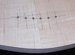
Now it is time to lay out the holes for the bridge pole pieces. These have to be very precise, as the tune-o-matic bridge doesn't allow for any slop. They must be precisely 2 29/32" apart (why that strange spacing? Who knows!) Also, the bass side of the bridge has to sit approximately 1/8" farther from the nut than the trebel side. This is to account for what is known as compensation. Compensation is a discussion that is far deeper than what I want to get into here, so let's just say that if I don't allow for an extra 1/8" on the bass side, the instrument might not intonate correctly. Once I had the layout holes marked, I drilled them out. Also, I don't have a photo of this (wife was using the camera at the moment) but I also drilled a small hole (1/8") in the right bridge post hole through to the control cavity using another extra long drill bit. This will allow me to pass a ground wire through the hole and ground the bridge, which is very important in keeping the guitar quiet and buzz-free.
The last real "shaping" activities remaining on the guitar body prior to gluing in the neck are installing the binding and drilling the hole for the output jack. The binding actually needs to be done first, as I didn't want to have to figure out how to get around the jack hole while routing the binding channel. However, because installing the binding was a fairly complex process I wanted to describe it in it's own web page. So the following description of drilling the jack hole is a little out of sequence.
Rather than a standard "hole in the side of the guitar" for the output jack, or the Strat method of using a plate on the front, I wanted to do something a little different to help make this guitar my own unique creation. Back in the '80's, Hamer produced a guitar called the "Californian" which was your super-shredder type axe. I think they still make this model under their imported "Slammer" series, but I digress. One of the features I always liked about this particular guitar was how the output jack was angled upwards towards the strap button. This was done because many guitarists loop their cord over the strap button, between the strap and the body. By doing this, the annoyance of stepping on your guitar cable (we all do it) will remain a mere annoyance rather than unplugging your axe mid-performance. By angling the output jack, it makes it easier to accomodate this practice.
To drill this angle, I clamped the guitar to a piece of wood that would hold it in the proper position.
At this point, I ran into my first limitation ever with a bench-top drill press. Even with the press table all the way down, I didn't have enough height to fit the body under the chuck. Rather than going out and buying or borrowing somebody's floor standing drill press (the proper method) I decided to put some of my cheapness into action and rigged a hokey way to do it with the bench-top press. I should have gotten a picture of this, but I didn't (which is probably good because it really wasn't the proper way of doing things and I don't want to condone this sort of thing.)
What I wound up doing was placing the drill press on some pieces of scrap wood to raise it up a couple inches. Then, I loosened the allen head bolts holding the press head on the shaft, and rotated it 90 degrees off of parallel (why didn't I just say perpendicular?) to the base. By doing these two things, I could slip the guitar body under the quill and drill the holes. Unfortunately, I learned that because the press wasn't heavy enough, putting pressure on the quill caused the press to tilt, so I had to bear-hug the workpiece and press to try and keep everything lined up correctly. It isn't the most accurate hole I've ever drilled, but I got it done. Looks like it's time to graduate to a floor-mounted press.
Anyway, the access hole was done in two steps. First, I drilled a 3/4" hole about an inch into the body (did it by eye as the depth really didn't have to be that precise.) Then, in the center of that hole I drilled a 1/2" hole in which to mount the jack socket.
We're slowly getting there. The next step is to install the body binding.
Or if you like, you can go back to the main body blank creation.
Return To The Main Music Gallery
This page last updated on 06/28/2018